
Airbreathing fuel cell

a fuel cell and air-breathing technology, applied in the field of air-breathing fuel cells, can solve the problems of insufficient operation of the load object and inability to adequately achieve the positioning of the center, and achieve the effect of increasing the flow ra

Inactive Publication Date: 2006-10-10
DAIDO METAL CO LTD
View PDF2 Cites 8 Cited by
  • Summary
  • Abstract
  • Description
  • Claims
  • Application Information

AI Technical Summary

Benefits of technology

[0011]The invention has been thought of in view of the problem, and has its object to provide an airbreathing fuel cell, in which a fuel can be adequately supplied to a cell part from outside even at a low fuel pressure and replacement with an air can be easily made to obtain a stable power generating performance.
[0012]Also, another object of the invention is to provide an airbreathing fuel cell, in which a fuel distribution manifold is made use of to position respective constituent members of a cell stack at the time of assembly in a manner to eliminate out-of-center.

Problems solved by technology

Therefore, when used for a load, for which a comparatively large electric current is needed, it cannot be said that a flow rate of hydrogen supplied is adequate, and consequently a characteristic of power generation becomes unstable in some cases to cause an object of load to be insufficient in operation.
That is, with a fuel distribution manifold such as a hydrophilic synthetic fiber sleeve, out-of-center can be decreased but positioning of centers cannot be adequately effected due to elasticity, and so such sleeve is not used in the case of accommodating for a load of low electric power, in which there is no need of taking account of generation of moisture.

Method used


Image

  • Airbreathing fuel cell
  • Airbreathing fuel cell
  • Airbreathing fuel cell

Examples


Embodiment Construction

[0025]Embodiments of the invention will be described in detail below with reference to the drawings.

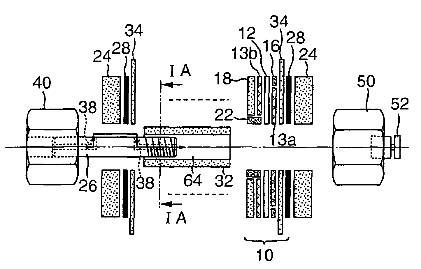
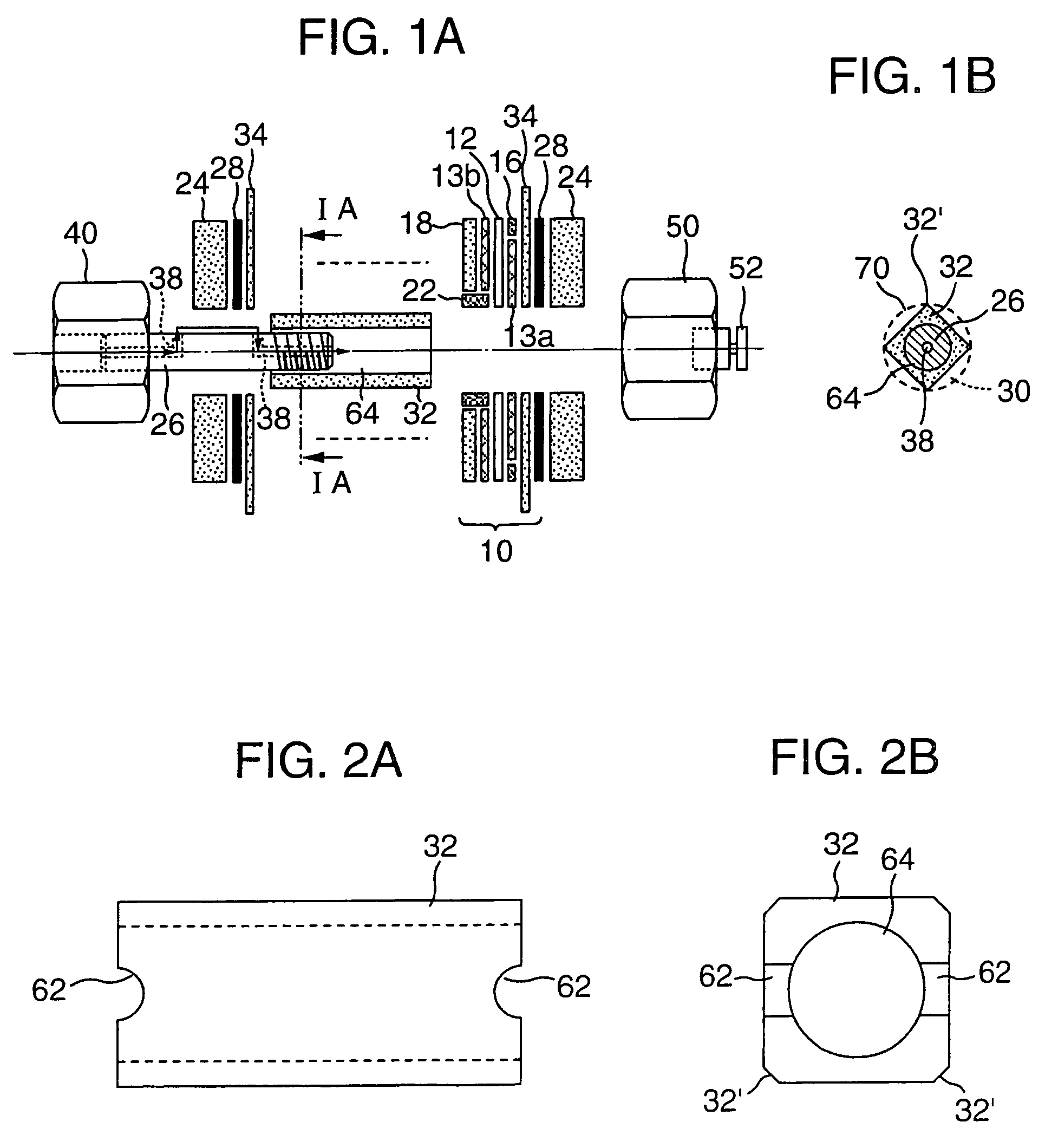
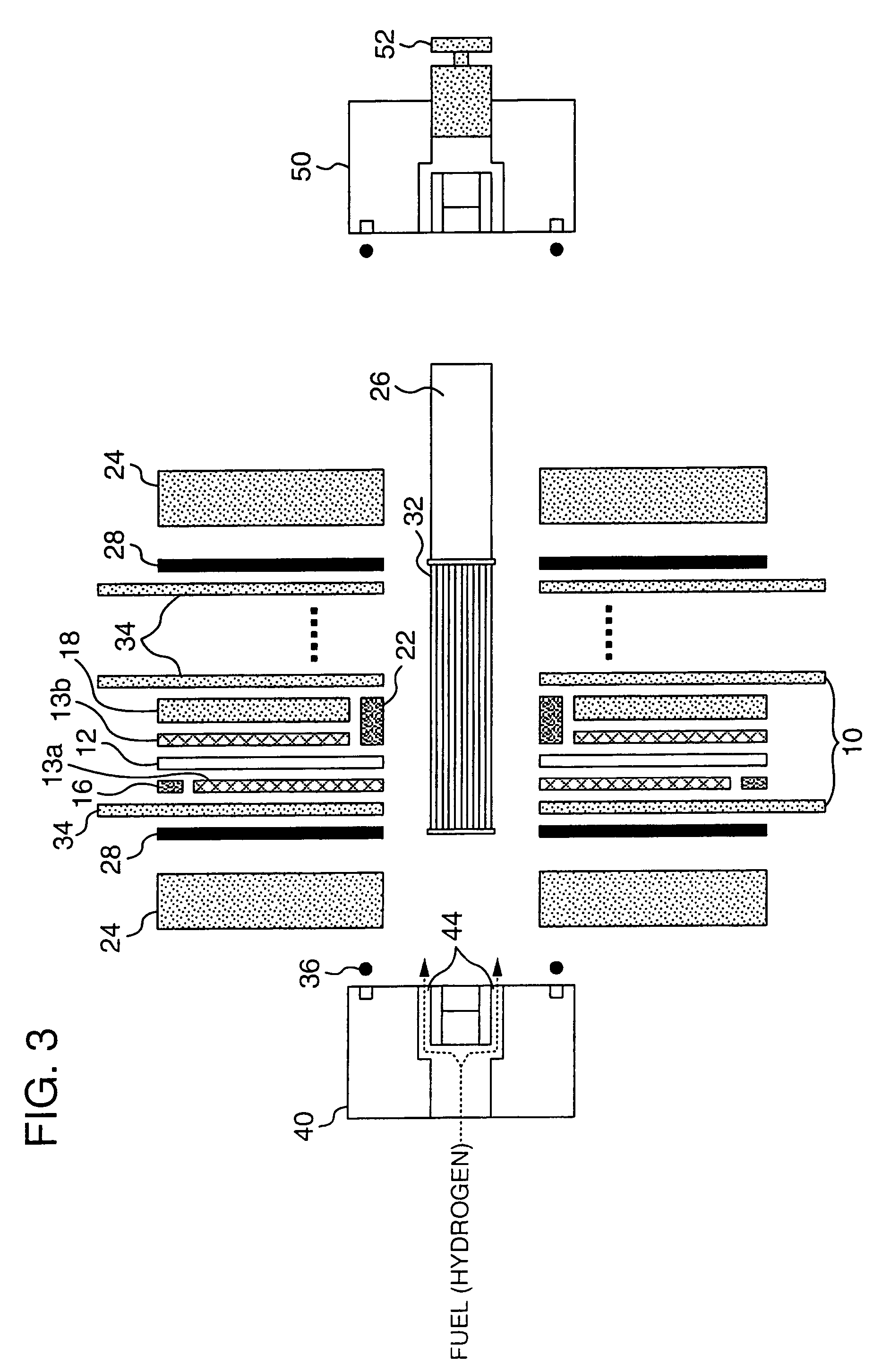
[0026]Referring to FIGS. 1A, 1B and 2A, 2B, FIG. 1A is an exploded, partially cross sectional view showing an airbreathing fuel cell according to an embodiment of the invention, and FIGS. 2A and 2B are a front view and a side view showing a fuel distribution manifold used in the airbreathing fuel cell. In the airbreathing fuel cell shown in these figures, members having the same constitution as that of conventional ones shown in FIG. 3 are denoted by the same reference numerals and described. With the airbreathing fuel cell, a plurality of single cells 10, respectively, constituting a cell stack are conventionally configured as shown in FIG. 3, and comprise an oxygen passage plate 18 interposed between an oxygen electrode 13b supported by an inner seal 22 and a separator plate 34.

[0027]Also, the oxygen passage plates 18 are made of a carbon plate, and the oxygen passage plates 18 and ...


PUM

PropertyMeasurementUnit
power densityaaaaaaaaaa
hydrophilicaaaaaaaaaa
sizeaaaaaaaaaa

Abstract

An airbreathing fuel cell, in which a fuel can be adequately supplied to a cell part from outside even at low fuel pressures and air replacement can be easily performed to provide a stable power generating capacity, comprises a cell stack formed by stacking a plurality of those unit cells, which comprise a solid polymer electrolyte membrane, an oxygen passage plate and a fuel electrode, which are provided on both sides of the solid polymer electrolyte membrane to be opposed to each other, the oxygen passage plate provided adjacent and toward the oxygen electrode, and separator plates provided adjacent and outside the oxygen passage plate and the fuel electrode, the fuel distribution manifold being formed into a rod-shaped body having a polygonal-shaped cross section, a fuel supply passage formed in the tie bolt, and a plurality of fuel distribution passages provided to be communicated to the fuel supply passage and formed between central holes of the unit cells and an outer peripheral surface of the fuel distribution manifold.

Description

BACKGROUND OF THE INVENTION[0001]1. Technical Field[0002]The present invention relates to a fuel cell usable for various usages such as electric sources and electric generators for outdoor, pleasure trip, household, business machines, or the like, and more particular, to an airbreathing fuel cell capable of supplying a sufficient amount of fuel into cells in a pollution-free polymer electrolyte fuel cell.[0003]2. Background Art[0004]Among fuel cells, a solid electrolyte fuel cells with hydrogen as a main fuel has been given attention and developed because of low working temperature and high power density (see, for example, Patent document 1 and Patent document 2).[0005]As an example of such fuel cells, the inventors of the present application have proposed an airbreathing fuel cell, in which unit cells having a circular-shaped cross section are stacked (see Patent document 2). Concretely, a unit cell 10 comprises, as shown in an exploded figure in FIG. 3, an anode (fuel electrode) 1...

Claims


Application Information

Patent Timeline
Patent Type & Authority Patents(United States)
IPC IPC(8): H01M2/14H01M8/02H01M8/10H01M8/04H01M8/24
CPCH01M8/02H01M8/04089H01M8/2465H01M8/248Y02E60/50H01M8/2483H01M8/0271H01M8/2432
Inventor KATO, EIJINARUSE, YUKIOOWAKI, NOBORUNAWA, SHOJIIDO, YASUO
Owner DAIDO METAL CO LTD
Learn More