High frequency oscillator using transmission line resonator

a transmission line resonator and high frequency technology, applied in the field of high frequency oscillators, can solve the problems of affecting the operation of the oscillator, so as to achieve the effect of high frequency

Inactive Publication Date: 2006-10-10
NIHON DEMPA KOGYO CO LTD +1
View PDF4 Cites 7 Cited by
  • Summary
  • Abstract
  • Description
  • Claims
  • Application Information

AI Technical Summary

Benefits of technology

[0020]It is an object of the present invention to provide a high frequency oscillator which is capable of generating a frequency component four times higher than a fundamental wave of oscillation, and lends itself to a reduction in size.
[0023]The plurality of output lines are respectively coupled to the transmission line resonator at maximum displacement distribution points for a standing wave of 2n-th harmonic, at which the standing wave is in opposite phase to that at the midpoint. Consequently, the 2n-th harmonics are combined in phase and delivered from the connection. On the other hand, as to second to 2(n−1)-th harmonics, some of standing waves associated with these harmonics have null potential at the positions at which the output lines are connected to the resonator. Other harmonic components are also combined in opposite phases at the connection, and as a result delivered at null potential. While 2(n+1)-th and higher harmonics are also generated, they are relatively low in level and can be readily removed by a simple filter, with the result that the 2n-th harmonic alone is generated as an oscillation output.
[0024]According to the present invention, since a fourth harmonic or an eighth harmonic of a fundamental frequency, for example, can be generated only by connecting negative resistive active devices respectively at a pair of resonance wave points for a transmission line resonator which is a resonator for the fundamental wave, a high frequency oscillator can be readily reduced in size. Also, the high frequency oscillator of the present invention is suitable for incorporation into MMIC (Monolithic microwave integrated circuit).

Problems solved by technology

The high frequency oscillators configured as described above, however, have the following problems.
However, since a fourth-harmonic oscillator requires a pair of second-harmonic oscillators which cause the resulting oscillator to be large in size, and therefore hampers a reduction in size of the oscillator.
Likewise, for providing a 2n-th harmonic oscillator for generating an eighth harmonic or a higher-order harmonic (n≧3), a pair of 2(n−1)-th harmonic oscillators are required, and further hamper a reduction in size of the oscillator.

Method used


Image

  • High frequency oscillator using transmission line resonator
  • High frequency oscillator using transmission line resonator
  • High frequency oscillator using transmission line resonator

Examples


first embodiment

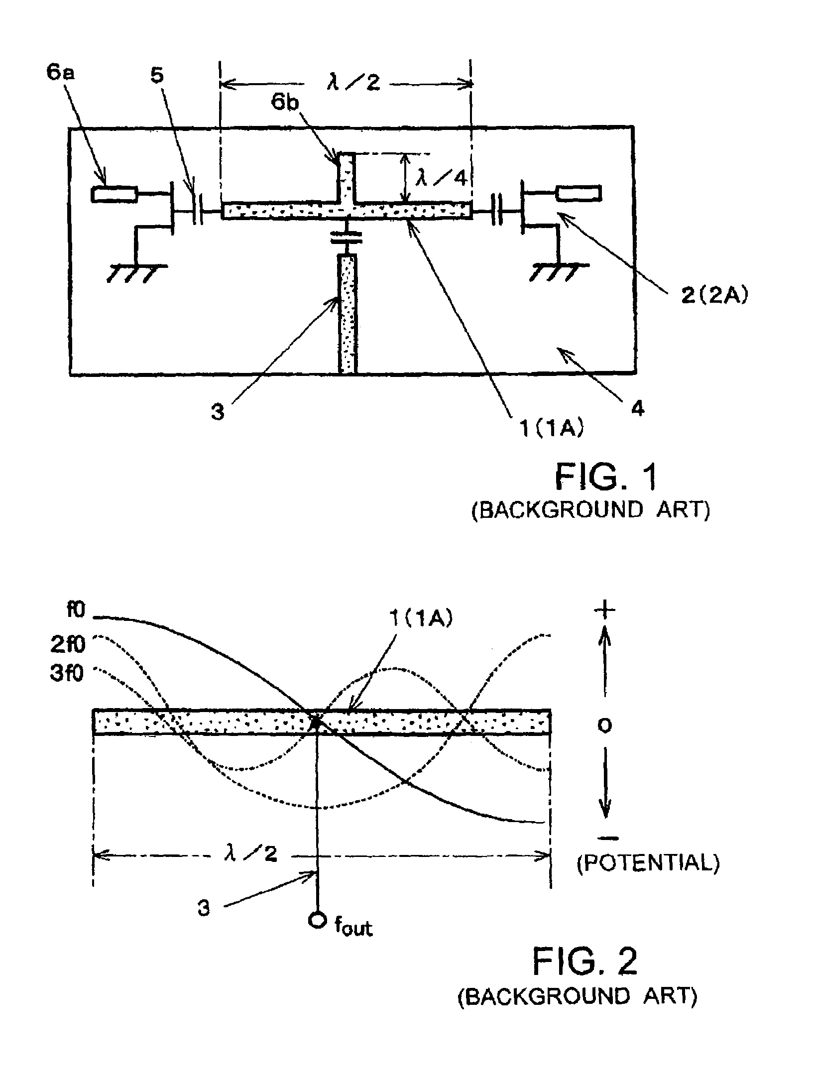
[0044]A high-frequency oscillator according to the present invention, illustrated in FIG. 5, employs a linear microstrip line resonator as a transmission line resonator, and is designed to function as a fourth-harmonic oscillator which generates a signal having a frequency four times as high as a frequency of fundamental wave f0 . . . . In FIG. 5, components identical to those in FIGS. 1 and 3 are designated the same reference numerals, and repeated description thereon is simplified.

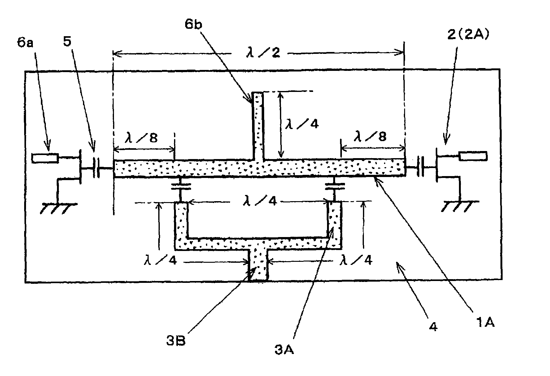
[0045]The fourth-harmonic oscillator illustrated in FIG. 5 comprises linear microstrip line resonator 1A having a length of λ / 2, where λ is the wavelength of fundamental oscillation frequency (fundamental wave) f0; negative resistive active devices (FETs 2A) connected at both ends of microstrip line oscillator 1A, respectively; two first output lines 3A; and second output line 3B. These resonator 1A, FETs 2A, and output lines 3A, 3B are disposed on one principal surface of dielectric substrate 4, while a...

second embodiment

[0054]FIG. 9 illustrates a high frequency oscillator according to the present invention which is configured to function as an eighth-harmonic oscillator though it has a similar configuration to that illustrated in FIG. 5. In FIG. 9, components identical to those in FIG. 5 are designated the same reference numerals and repeated description thereon is simplified.

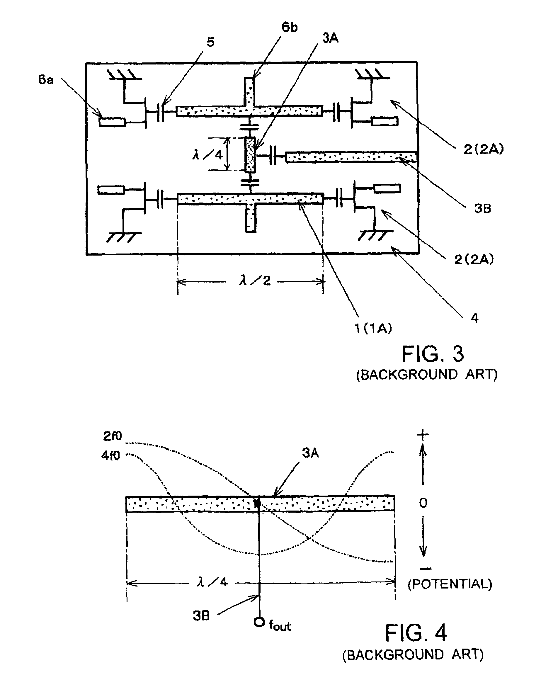
[0055]The eighth-harmonic oscillator comprises microstrip line resonator 1A having a length of λ / 2, where λ is the wavelength corresponding to the fundamental frequency (fundamental wave) of oscillation; negative resistive active devices (FETs 2A) connected to both ends of microstrip line resonator 1A, respectively, and having their oscillation waveforms distorted by bias setting; first output lines 3A; and second output line 3B, in a manner similar to the fourth-harmonic oscillator illustrated in FIG. 5. This fourth-harmonic oscillator has, however, four first output lines 4A.

[0056]Likewise, in the configuration of the second...

third embodiment

[0066]A high frequency oscillator according to the present invention illustrated in FIG. 13 is a fourth-harmonic oscillator which employs a microstrip line resonator formed in a loop shape to function as a loop-shaped transmission line resonator.

[0067]Annular microstrip line resonator 1B is formed on one principal surface of substrate 4 made of a dielectric material. The overall length of microstrip line resonator 1B, i.e., the perimeter of the annular ring is equivalent to one wavelength of fundamental wave f0. A ground conductor is disposed substantially over the entirety of the other principal surface of substrate 4. The wavelength of fundamental wave f0 is represented by λ. Negative resistive active devices (FETs 2A) are connected at both ends of a certain diameter of microstrip line resonator 1B, at a right end and a left end of resonator 1B in FIG. 13 through capacitors 5 for loose coupling, respectively. Therefore, both negative resistive active devices are spaced by λ / 2 away...


PUM


Abstract

A high frequency oscillator comprises a transmission line resonator having a midpoint which serves as a null potential point, a pair of active devices for oscillation respectively connected to a pair of mutually opposite-phase resonance wave points for the transmission line resonator, and a plurality of output lines each having one end connected to the transmission line resonator at a point symmetric to the midpoint, and the other end commonly connected to a connection. The pair of active devices share the resonator and oscillate in opposite phases to each other. The plurality of output lines are coupled to the transmission line resonator respectively at maximum displacement distribution points for a standing wave of an 2n-th harmonic in the transmission line resonator, where n is an integer equal to or larger than two. Even-order harmonic components of 2(n−1)-th or lower are suppressed at the connection.

Description

BACKGROUND OF THE INVENTION[0001]1. Field of the Invention[0002]The present invention relates to a high frequency oscillator for oscillating signals in a millimeter-wave band and a microwave band, and more particularly, to a high frequency oscillator which employs a transmission line resonator and is suitable for generation of a frequency four times or more higher than a fundamental oscillation frequency (i.e., fundamental wave) based on the resonator.[0003]2. Description of the Related Art[0004]High frequency oscillators suitable for generating oscillation signals in a millimeter-wave band and a microwave band are employed, for example, in optical communication systems and peripheral apparatuses associated therewith, and are required to improve the performance and reduce the cost. The present inventors have previously proposed such a high frequency oscillator which is a push-push oscillator using a transmission line resonator in Japanese Patent Laid-open Publication No. 2003-152455...

Claims


Application Information

Patent Timeline
Patent Type & Authority Patents(United States)
IPC IPC(8): H03B5/12H01P5/12H03B1/00H03B5/18H03B19/18
CPCH03B5/1852
Inventor AIKAWA, MASAYOSHITANAKA, TAKAYUKIASAMURA, FUMIOOITA, TAKEO
Owner NIHON DEMPA KOGYO CO LTD
Why Eureka
Try Eureka