
Method and system for improved ATE timing calibration at a device under test

a technology of digital integrated circuits and calibration methods, applied in the field of high-performance digital integrated circuit systems, can solve the problems of prior art calibration methods, which require calibration measurements at low speed, and the assumption of error mechanisms for a conventional device-under-test (dut) is increasingly inaccurate, and achieves accurate and reliable testing of modern high-speed integrated circuit devices. high performance, accurate timing propagation delay calibration

Active Publication Date: 2006-10-10
CREDENCE SYSTEMS
View PDF4 Cites 31 Cited by
  • Summary
  • Abstract
  • Description
  • Claims
  • Application Information

AI Technical Summary

Benefits of technology

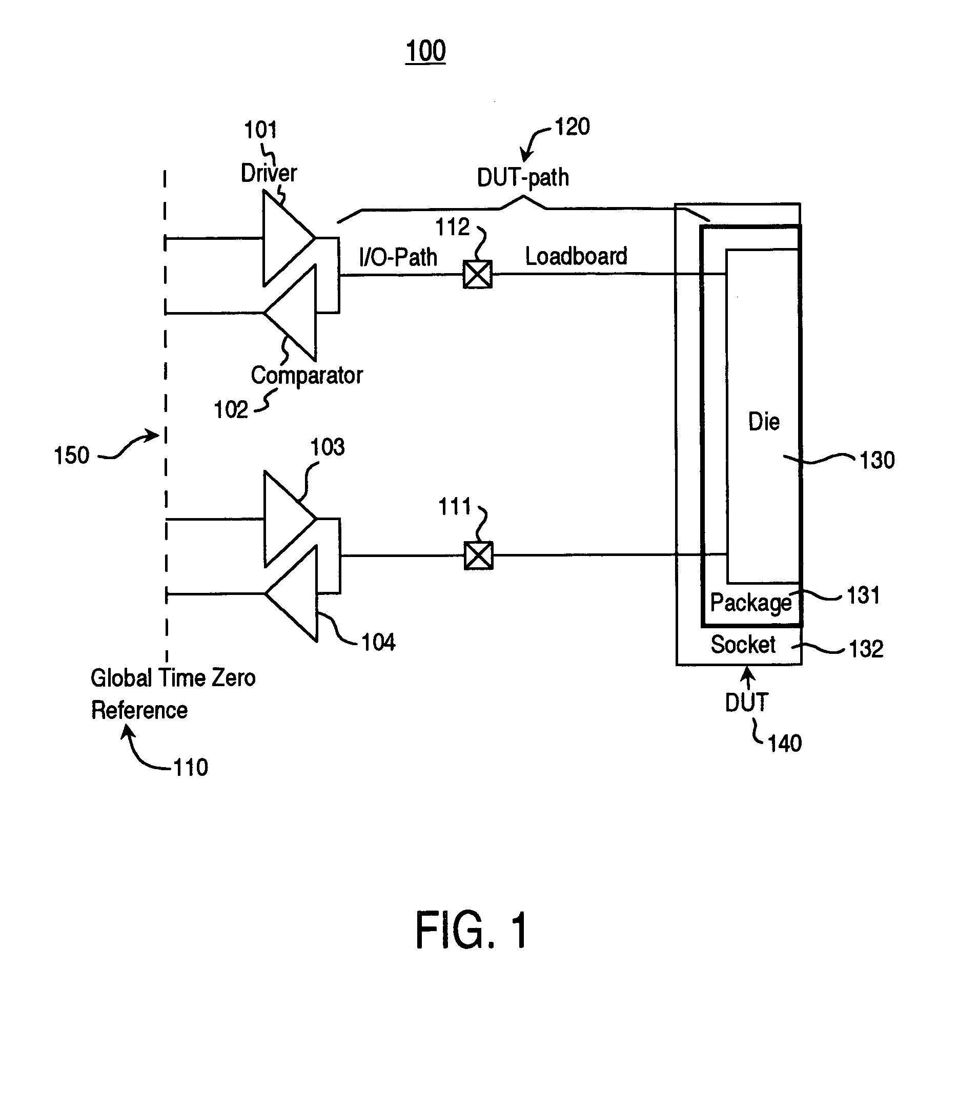
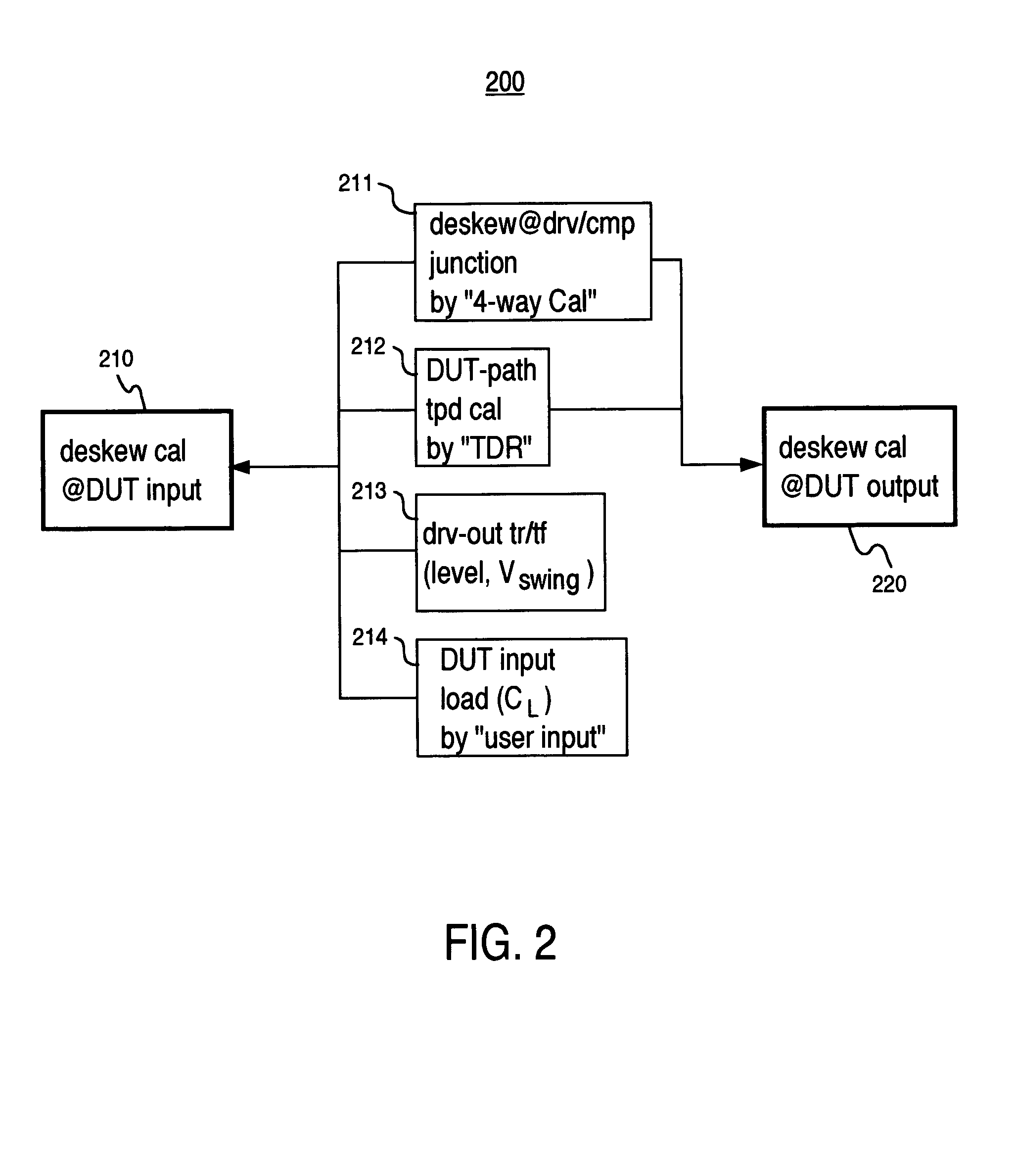
[0007]Embodiments of the present invention comprise a method and system for improved ATE timing calibration at a device under test that can accurately and reliably test modern high speed integrated circuit devices. Embodiments of the present invention are capable of accounting for error sources such as DDJ, pin-to-pin skew, and calibration errors in a testing and verification process for a high performance DUT.
[0009]In this manner, the physical calibration results combined with the simulation based calibration results provide a solution that can accurately and reliably test modern high speed integrated circuit devices. Modern simulation techniques are capable of accounting for error sources such as DDJ, pin-to-pin skew, and calibration errors in a testing and verification process for a high performance DUT in a way that is not possible using traditional physical calibration techniques alone. Since modern simulation techniques (e.g., once the simulation's accuracy is validated) are used for modeling the ATE to DUT signals paths, accurate timing propagation delay calibration can be performed on DUT components operating in the multi-Gbps range.

Problems solved by technology

One reason for the deficiency of the prior art is the fact that the conventional timing calibration error mechanisms do not accurately apply to high speed applications.
Assumptions about the error mechanisms for a conventional device-under-test (DUT) are increasingly inaccurate as signal data rates increase into the mult-Gbps range.
DDJ is, however, one of the major error sources in multi-Gbps testing, and therefore needs to be properly accounted for, and calibrated out, for higher timing accuracy.
For DDJ calibration, at-speed calibration measurement is essentially required, and therefore the prior art calibration methods, which necessitate calibration measurements at low speed, are not applicable.
Another problem is the fact that as signal data rates increase into the multi-Gbps range, the conventional prior art practice of modeling the ATE to DUT signals paths as simple transmission lines is no longer valid.
At the multi-Gbps speeds, a number of different error sources quickly become significant and can no longer be ignored.
Such error sources include, for example, DDJ timing error, pin-to-pin skew, and calibration errors at the DUT.
These problems render the prior art testing methodology insufficient for modern high speed, high performance integrated circuit devices.
Another problem is the fact that as signal data rates increase into the multi-Gbps range, the conventional prior art practice of modeling the ATE to DUT signals paths as simple transmission lines with a few lumped parasitic capacitors and inductors is no longer valid.

Method used


Image

  • Method and system for improved ATE timing calibration at a device under test
  • Method and system for improved ATE timing calibration at a device under test
  • Method and system for improved ATE timing calibration at a device under test

Examples


example simulation

Results with K28.5 Bit Pattern:

[0063]Simulation results are now described to illustrate the manner in which DDC in accordance with embodiments of the present invention function. In one example, a simulated circuit consists of three stages of packaged high speed buffers using bipolar transistor technology with lossy interconnects between them. Since a well-known “K28.5” pattern is often used for DDJ evaluation of telecom / datacom physical layer components and it contains a variety of bit patterns in only 20 bits duration, this pattern is the basis of the following discussions.

[0064]FIG. 14 shows a graph 1400 illustrating input and output waveforms associated with a K28.5 pattern. Graph 1400 shows the input and output waveforms where 1 UI is 300 ps. The input waveform is the square waveform indicated by line 1401. The output waveforms is indicated by line 1402.

[0065]FIG. 15 shows an “eye diagram” of the output waveform 1402. Lines 1501 and 1502 show the existence of about 35 ps DDJ. It...


PUM


Abstract

A method for improved ATE (automatic test equipment) timing calibration at a DUT (device under test). The method includes step of accessing a DUT component using an ATE component and performing physical calibration on a first portion of signal pathways coupling the ATE component to the DUT component. A simulation based calibration is performed on a second portion of signal pathways coupling the ATE component to the DUT component. The physical calibration results are combined with simulation based calibration results to calibrate timing propagation delay between the ATE component and the DUT component.

Description

FIELD OF THE INVENTION[0001]The field of the present invention relates to test methodology for high performance digital integrated circuit systems.BACKGROUND OF THE INVENTION[0002]Modern digital integrated circuit devices are achieving very high data processing speeds. For example, many widely used serial communication integrated circuit devices routinely operate at data I / O rates of multi-gigabits per second (Gbps). Such ever increasing data rates have placed ever increasing demands on the automatic test equipment (ATE) used to test the devices. As operating speeds have increased, higher and higher ATE test timing accuracy is required. For example, to properly test I / O signals of a multi-gigabit signal, the ATE must reliably and accurately place test strobe edges for the signal with pico-second accuracy.[0003]Prior art conventional ATE methods are loosing their ability to keep pace with the edge placement accuracy requirements of high performance integrated circuit devices. One rea...

Claims


Application Information

Patent Timeline
IPC IPC(8): G06K5/04G01D18/00G06F11/00G01R31/28
CPCG01D5/00G01R31/3191G01D18/00
Inventor SHIMANOUCHI, MASASHI
Owner CREDENCE SYSTEMS
Learn More