
Method for forming a write head having air bearing surface (ABS)

a technology of air bearing surface and write head, which is applied in the field of magnetic head fabrication, can solve the problems of write pole, inability to use plating, and inability to meet the requirements of magnetic recording,

Inactive Publication Date: 2006-10-17
HITACHI GLOBAL STORAGE TECH NETHERLANDS BV
View PDF23 Cites 83 Cited by
  • Summary
  • Abstract
  • Description
  • Claims
  • Application Information

AI Technical Summary

Benefits of technology

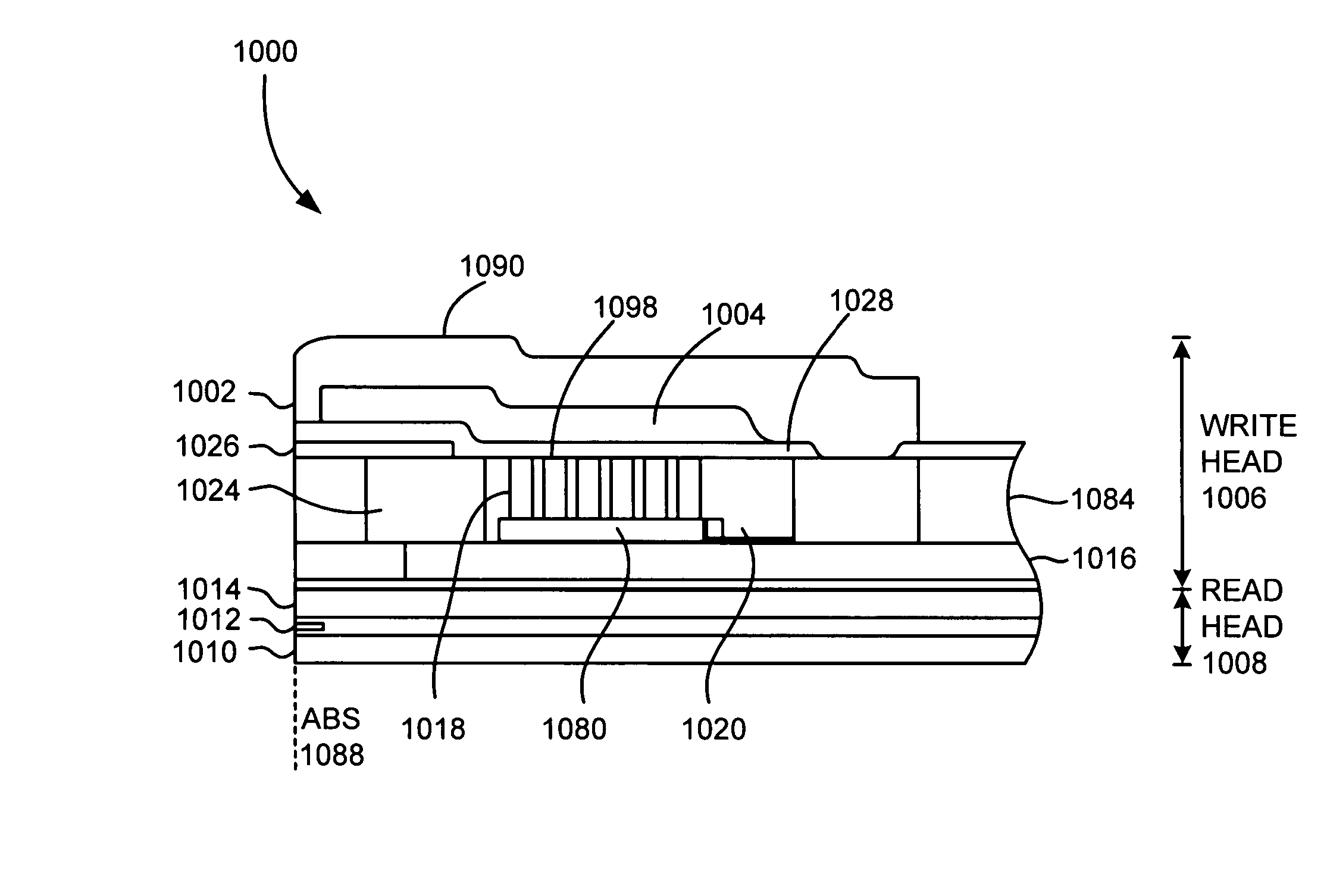
[0032]A layer of dielectric material is deposited above the (material covering the) pole tip and flux shaping layer, where the layer of dielectric material extends about adjacent to the mask layer. Preferably, the mask layer is comprised of a bilayer of durimide and carbon collectively functioning as the mask layer. This increases the overall thickness of the mask layer and its ion mill resistance. When the dielectric material is deposited, it should abut the carbon layer which functions as a CMP stop layer. A stop layer is deposited over the dielectric material, the stop layer abutting the mask layer.
[0034]As an optional step, the mask layer may be removed prior to forming the gap layer, and dishing formed in the upper surface of the pole tip. It has surprisingly been found that a little dishing into the pole tip straightens out the transition field. The extent of dishing also aids in creation of the gap thickness. The mask layer can be removed by additional polishing or etching (e.g., reactive ion etching). The dishing can be formed by etching (e.g., sputter etching) or by polishing.

Problems solved by technology

At these dimensions, write pole instability (reminiscent issues, e.g., writing continuing after power to head is terminated) becomes an issue and requires implementing lamination technology in the write pole.
Lamination, however, forecloses use of plating to form the write pole.
The difficulty in fabricating a trailing shield write pole is designing a process to have tight control of the write gap and fabricating a structure on top of the write gap with minimal damage to the write gap or write pole.
However, due to the need to implement lamination to reduce write instability these technologies were found to be undesirable.
Moreover at submicron trackwidth dimension, the pole piece as fabricated by ion milling will be fragile and removal of redeposited materials on top (redeposition) and sides (fencing) of the pole will be increasingly more difficult.

Method used


Image

  • Method for forming a write head having air bearing surface (ABS)
  • Method for forming a write head having air bearing surface (ABS)
  • Method for forming a write head having air bearing surface (ABS)

Examples


Embodiment Construction

[0056]The following description is the best embodiment presently contemplated for carrying out the present invention. This description is made for the purpose of illustrating the general principles of the present invention and is not meant to limit the inventive concepts claimed herein.

[0057]Referring now to FIG. 6, there is shown a disk drive 600 embodying the present invention. As shown in FIG. 6, at least one rotatable magnetic disk 612 is supported on a spindle 614 and rotated by a disk drive motor 618. The magnetic recording on each disk is in the form of an annular pattern of concentric data tracks (not shown) on the disk 612.

[0058]At least one slider 613 is positioned near the disk 612, each slider 613 supporting one or more magnetic read / write heads 621. More information regarding such heads 621 will be set forth hereinafter during reference to the remaining FIGS. As the disks rotate, slider 613 is moved radially in and out over disk surface 622 so that heads 621 may access ...


PUM

PropertyMeasurementUnit
thicknessaaaaaaaaaa
widthaaaaaaaaaa
thicknessaaaaaaaaaa

Abstract

A method and materials to fabricate a trailing shield write pole that resolve the problems of controlling the write gap and preventing damages to the write gap or pole during fabrication of the subsequent structure. This process also introduces a CMP assisted lift-off process to remove re-deposition and fencing (increase yields) and a method to create dishing in the top of the write pole. Moreover, also included in this disclosure are suitable materials that can function as an ion mill transfer layer, CMP layer, and RIEable layer.

Description

FIELD OF THE INVENTION[0001]The present invention relates to magnetic heads, and more particularly, this invention relates to fabrication of a head having a trailing shield structure.BACKGROUND OF THE INVENTION[0002]In a typical head, an inductive write head includes a coil layer embedded in first, second and third insulation layers (insulation stack), the insulation stack being located between first and second pole piece layers. A gap is formed between the first and second pole piece layers by a gap layer at an air bearing surface (ABS) of the write head. The pole piece layers are connected at a back gap. Currents are conducted through the coil layer, which produce magnetic fields in the pole pieces. The magnetic fields fringe across the gap at the ABS for the purpose of writing bits of magnetic field information in tracks on moving media, such as in circular tracks on a rotating magnetic disk or longitudinal tracks on a moving magnetic tape.[0003]The second pole piece layer has a ...

Claims


Application Information

Patent Timeline
Patent Type & Authority Patents(United States)
IPC IPC(8): G11B5/127C23C14/00G11B5/012G11B5/11G11B5/33
CPCG11B5/112G11B5/1278Y10T29/49067Y10T29/49032Y10T29/49043Y10T29/49041Y10T29/49021Y10T29/49048Y10T29/49044Y10T29/49046Y10T29/49052
Inventor LE, QUANGLEE, EDWARD HIN PONGLI, JUI-LUNGPENTEK, ARONSUN, NIAN-XIANG
Owner HITACHI GLOBAL STORAGE TECH NETHERLANDS BV
Learn More