Rolling support device and method for manufacturing the same

a support device and rolling support technology, applied in the direction of manufacturing tools, furnaces, heat treatment devices, etc., can solve the problems of difficult carburizing, lack of mass productivity, and difficulty in gas carburizing surface layers, so as to improve durability and cost, the effect of increasing the cos

Inactive Publication Date: 2006-10-17
NSK LTD
View PDF9 Cites 20 Cited by
  • Summary
  • Abstract
  • Description
  • Claims
  • Application Information

AI Technical Summary

Benefits of technology

[0021]As described above, the present inventors have accomplished the invention based on the finding that a rolling support device more excellent in the corrosion resistance and the durability can be provided by using an austenitic stainless steel and fabricating the same into a desired shape, then removing a passivation layer comprising a Cr oxide layer to activate the surface by fluoriding and then forming a carburizing hardened layer containing no substantial carbides in the surface layer.
[0052]The restrictions described above are at least for the moving member and such restrictions are not applied to other constituent components (fixed member or rolling element), and bearing steels such as SUJ2 or martensitic stainless steel may also be used as the material. Further, the roiling element is preferably made of ceramics such as silicon nitride, zirconia, alumina or silicon carbide. Since this can reduce friction and wear between the rolling element and the raceway component, the durability can be improved further.

Problems solved by technology

It has been well-known that the austenitic stainless steels have a Cr oxide layer (passivation layer) on the surface and, accordingly, carburizing is difficult and modification of the surface layer by gas carburizing is not easy.
For example, ion nitriding or plasma carburizing is typical as the surface modification for the stainless steels but since this utilizes electric discharging phenomenon, they lack in the mass productivity and has a difficulty in forming a homogeneous treated layer to a product of a complicated shape.
Therefore, while it is preferred to adopt the surface modification by utilizing gas reaction, since oxide layers (Cr oxide layer described above) that hinder the gas reaction are present in the austenitic stainless steels, no uniform or homogeneous treated layer can be formed by existent nitriding or carburizing.

Method used


Image

  • Rolling support device and method for manufacturing the same
  • Rolling support device and method for manufacturing the same
  • Rolling support device and method for manufacturing the same

Examples


first embodiment

[0061]The mode of practicing the rolling device according to the present invention is to be described with reference to the drawings.

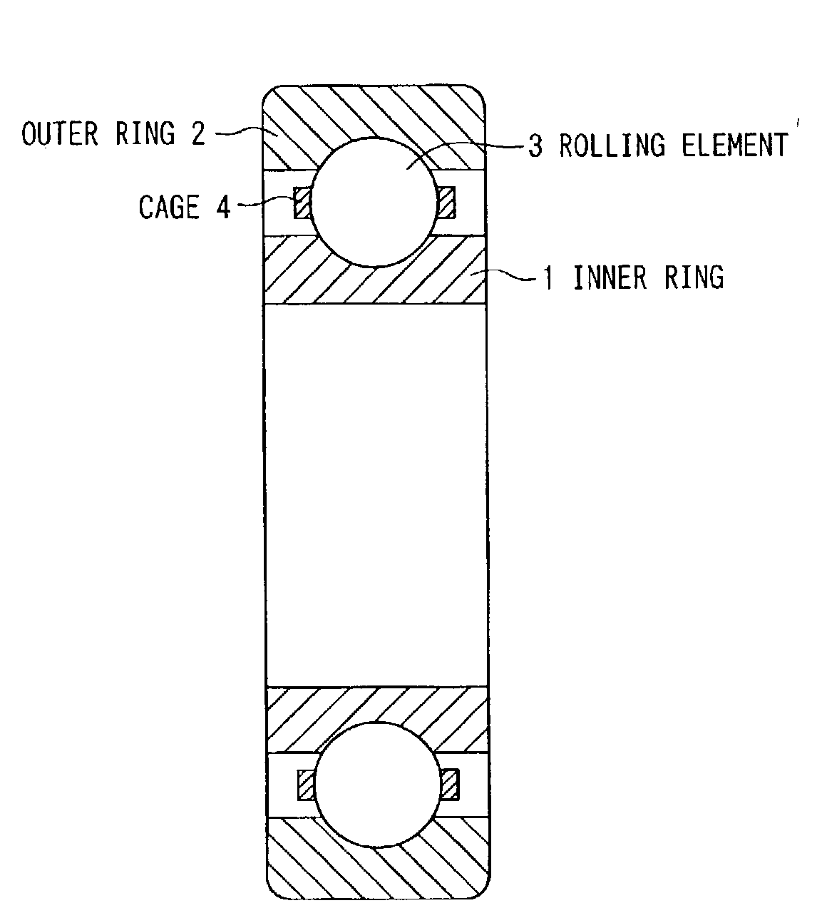
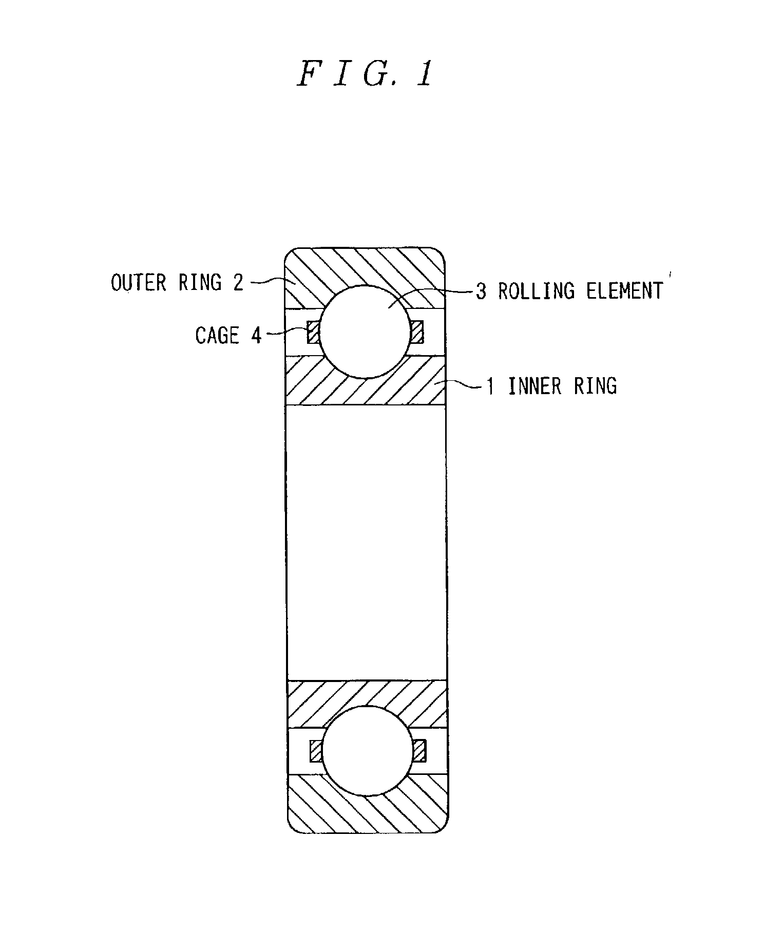
[0062]FIG. 1 is a cross sectional view of a rolling bearing as an embodiment of the present invention. The rolling bearing comprises a plurality of rolling elements (balls) 3, an inner ring (fixed member or a moving member) 1 situated inward thereof and an outer ring (fixed member or a moving member) 2 situating outward thereof in which the rolling elements 3 are guided under rolling while being held between the inner ring 1 and the outer ring 2. In this case, a rolling groove (rolling raceway surface) for guiding the rolling elements 3 is formed to the inner ring 1 and the outer ring 2, and the rolling elements 3 are held in the rolling groove by a cage 4 in an equally distributed arrangement.

[0063]In all examples and comparative examples of this embodiment, ball bearings 695 (JIS bearing number) were assembled as the rolling bearing having the struct...

second embodiment

[0097]Ball bearings of a JIS bearing No. 608 was manufactured as described below. The ball bearing comprises, as shown in FIG. 1, an inner ring (fixed member or moving member) 1, an outer ring (fixed member or moving member) 2, balls (rolling elements) 3 and a cage 4.

[0098]The inner ring and the outer ring are at first fabricated into a predetermined shape from various kinds of iron and steel materials shown in the following Table 3 by cutting a blank material by lathing. As the iron and steel materials, austenitic stainless steels (SUS 316, SUS 316L, SUS 316J1, SUS 317, SUS 317J1, SUS 303 and SUS 304) and Mn—Cr—Ni—V series precipitation hardening type austenitic non-magnetic steels (┌YHD 50┘ manufactured by Hitachi Kinzoku Co.) which were subjected to solid solution were provided.

[0099]Then, for the inner ring and the outer ring comprising the austenitic stainless steel, grinding finishing was applied and then fluoriding was applied under the following conditions. The fluoriding co...


PUM

PropertyMeasurementUnit
temperatureaaaaaaaaaa

Abstract

A rolling support device excellent in both of the characteristics of durability and corrosion resistance is provided. The inner ring (1) and the outer ring (2) comprises an austenitic stainless steel and has, on a raceway surface, a carburizing hardened layer containing no substantial carbides at a Vickers hardness (Hv) of 650 or more. The carburizing hardened layer is formed by applying fluoriding and then applying carburizing at a temperature of 540° C. or lower. The rolling element (3) is made of Si3N4.

Description

TECHNICAL FIELD[0001]The present invention relates a rolling support device (for example, rolling bearing, ball screw and linear motion guide) and, more in particular, it relates to a rolling support device suitable to application uses requiring high corrosion resistance and application uses requiring high corrosion resistance and non-magnetic property.BACKGROUND ART[0002]Heretofore, as the material for raceway member (fixed member and moving member having a rolling raceway surface) for a rolling support device, SUJ2 has been used for bearing steel and steel materials corresponding to SCR420 and SCM420 have been used for case hardening steels. Since the rolling support device is used generally under repetitive shearing stress at a high surface pressure, for ensuring rolling contact fatigue life endurable to the shearing stress, hardness is adjusted to HRC 58 to 64 by applying quenching and tempering for case the bearing steel and applying quenching and tempering after carburizing or...

Claims


Application Information

Patent Timeline
Patent Type & Authority Patents(United States)
IPC IPC(8): C23C8/20F16C33/30C21D1/06C21D9/40C22C38/00C22C38/44C23C8/22C23C8/26C23C8/34F16C33/32F16C33/62F16C33/64
CPCC23C8/02C23C8/22C23C8/34F16C33/32F16C33/62
Inventor TANAKA, SUSUMUITO, HIROYUKI
Owner NSK LTD
Why Eureka
Try Eureka