Magnetic resonance apparatus and operation method for hyperthermic treatment

a magnetic resonance and hyperthermic treatment technology, applied in the field of magnetic resonance installation, can solve the problems of different propagation speed of electromagnetic waves in the tissue and surrounding air, tumor-containing tissue to die, and the damage of the surrounding healthy tissue to a greater extent than the surrounding healthy tissue, and achieve the effect of sufficient focusing of the rf field and high level of accuracy

Inactive Publication Date: 2006-10-17
SIEMENS HEALTHCARE GMBH
View PDF28 Cites 19 Cited by
  • Summary
  • Abstract
  • Description
  • Claims
  • Application Information

AI Technical Summary

Benefits of technology

[0010]An object of the present invention is to provide an apparatus for selective hyperthermic treatment which allows sufficient focusing of the RF field without the use of water cushions and strain-free temperature measurement with a high level of accuracy.
[0013]The present embodiment of the magnetic resonance installation and the above-described operating method allow hyperthermic treatment of a patient without a water cushion. Actuation of each individual antenna using the correct amplitude and phase for the purpose of correctly focusing the RF field is ascertained in advance by detecting the amplitude and phase of the magnetic resonance signal received by each individual antenna from the body region which is to be treated. In this way, regardless of the anatomy of the patient and the interspace between the antennas and the patient, the correct amplitude and phase actuation is always achieved for optimum focusing of the RF field at the location of a region which is to be treated, particularly a tumor. It is thus possible to provide additional applicators, for example for physiological monitoring of the patient during the hyperthermic treatment, while the same magnetic resonance installation can be used to perform a temperature measurement with a high level of accuracy and without any strain on the patient.
[0017]In the case of the present magnetic resonance installation, each antenna also has a separate reception channel in order to be able to detect a magnetic resonance echo or signal which is induced in the antennas. To this end, the respective matching unit and the power amplifier preferably have a transmission / reception changeover switch arranged between them which forwards the magnetic resonance signal on each transmission antenna to a receiver circuit. The receiver circuit itself is produced by a preamplifier circuit and a demodulator circuit which can separate each individual received signal according to amplitude and phase. The receiver circuit can be equipped with an analog IQ demodulator or with a digital demodulator. This receiver circuit allows detection of the phase shifts and of the attenuation of the RF amplitude in the tissue surrounding the tumor.
[0018]The present magnetic resonance installation is designed to generate a sufficiently high magnetic resonance frequency which allows explicit focusing of the radio frequency field at the field strength of the basic field magnet. On the other hand, the field strength of the basic field magnet is chosen such that an explicit representation of the temperatures in the examined tissue is still achieved at the associated magnetic resonance frequency. For the field strength of the basic field magnet, a field strength of 3T is suitable, for example, which means that a magnetic resonance frequency of 123.2 MHz needs to be generated. This magnetic resonance frequency corresponds to a wavelength of 10–30 cm in the patient's body and 2.5 m in the air, which means that sufficiently intense focusing of the RF energy can be achieved.
[0023]Such a magnetic resonance measurement for ascertaining the correct phases and amplitudes for actuating the antennas can naturally also be repeated while the heating sequence is being carried out, by virtue of said heating sequence being briefly interrupted for the magnetic resonance measurement. In this way, it is possible to attain optimum focusing results even if the patient changes position during the treatment.

Problems solved by technology

Since the tumor-containing tissue is more heat sensitive than healthy tissue, the heating damages it to a greater extent than the surrounding healthy tissue.
Such targeted heat treatment can cause the tumor-containing tissue to die.
A fundamental problem in hyperthermic treatment is the different propagation speed of electromagnetic waves in the tissue and in the surrounding air.
This influences the focusing, however, which means that it has not always been possible hitherto to focus the RF energy in optimum fashion during hyperthermic treatment without further auxiliary means.
However, this procedure is an unpleasant experience particularly for claustrophobic patients.
In addition, simultaneous application of other applicators, for example for physiological monitoring of the patient during the hyperthermic treatment, is made more difficult by the water cushion, since little space remains for positioning additional applicators.
This invasive method, however, puts an additional strain on the patient.
One problem when applying a new approach to temperature measurement is the accuracy of the temperature measurement.
This accuracy is currently barely sufficient, since the hyperthermic applicator is arranged between the RF transmission and reception unit of the magnetic resonance installation and the patient, which means that the received signal from a magnetic resonance echo is received only very weakly by the magnetic resonance installation's RF transmission and reception unit.
Another cause of the insufficient accuracy of such temperature measurement is the choice of RF transmission frequency in the magnetic resonance installation.
To excite the magnetic resonance, however, the chosen magnetic resonance frequencies require magnetic field strengths in the basic field magnet of between 0.2 T and 1.5 T. At such basic field strengths, the temperature-dependent T1 T2 shift is not very distinct, however, which means that this also impairs the accuracy of the temperature determination.

Method used


Image

  • Magnetic resonance apparatus and operation method for hyperthermic treatment
  • Magnetic resonance apparatus and operation method for hyperthermic treatment
  • Magnetic resonance apparatus and operation method for hyperthermic treatment

Examples


Embodiment Construction

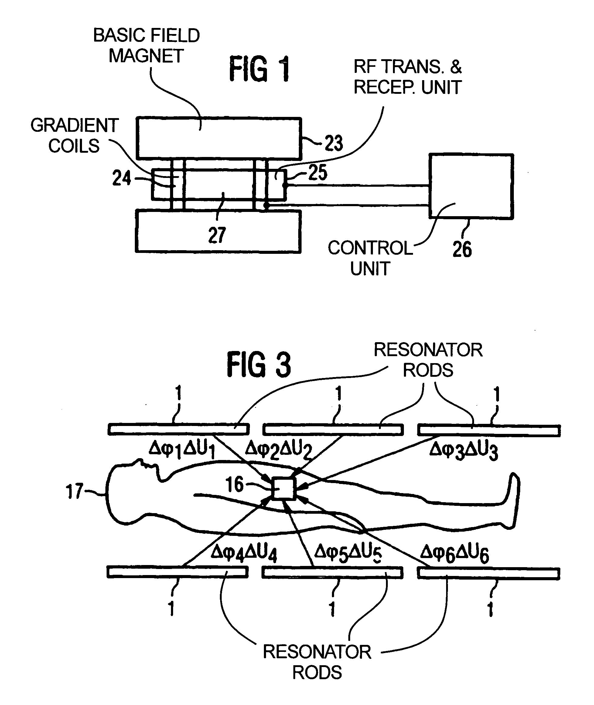
[0029]FIG. 1 shows a greatly simplified illustration of the basic design of a magnetic resonance installation in the form in which it is also produced for the present invention. FIG. 1 shows the basic field magnet 23, the gradient field coils 24, the RF transmission and reception unit 25 which surrounds the examination space 27, and also a control unit 26 for actuating the gradient field coils 24 and the RF transmission and reception unit 25. The units provided in magnetic resonance installations, such as evaluation computer, memory, pulse sequence controller, pulse shape generator or RF generator, are combined in the control unit 26 in this illustration.

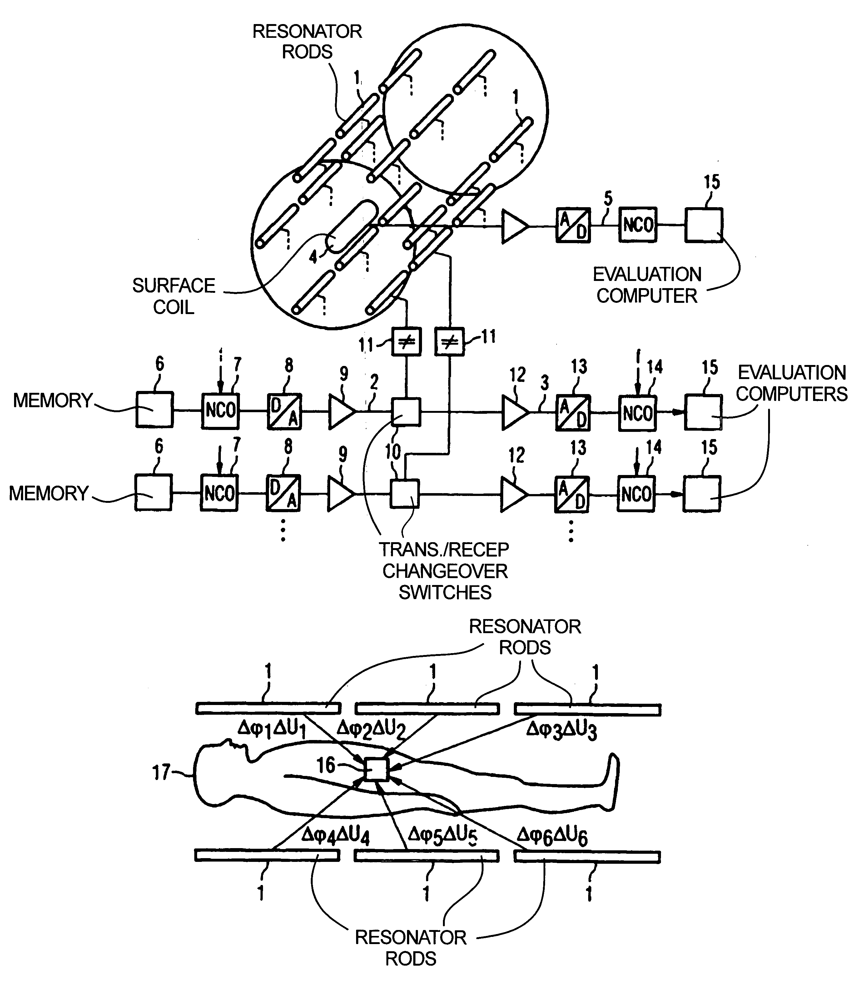
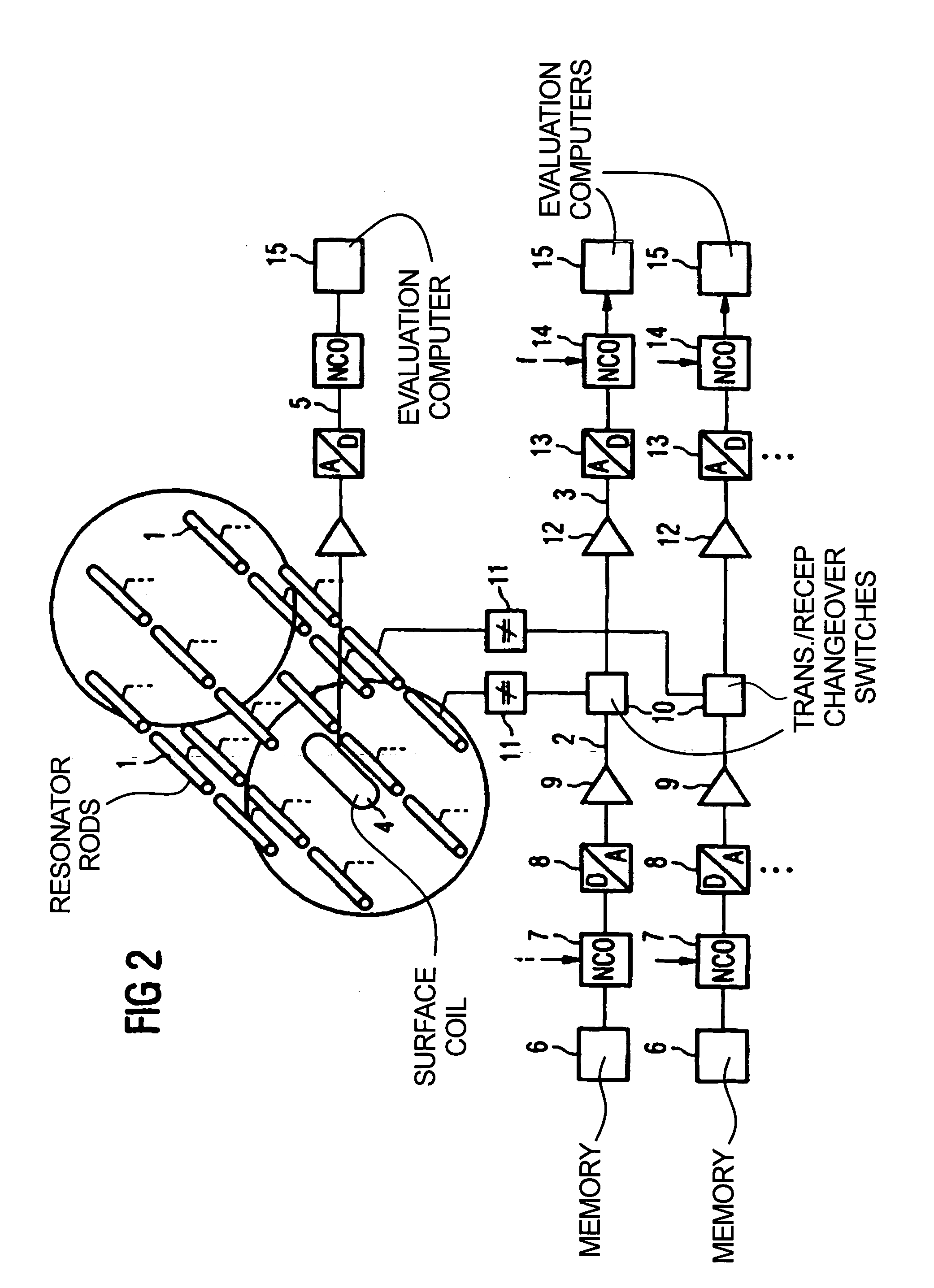
[0030]FIG. 2 shows, as an example, an embodiment of an RF transmission and reception unit in the form in which it is used in a magnetic resonance installation based on the present invention. The RF transmission and reception unit is made up of a multiplicity of resonator rods 1 which are arranged in array form and are arranged aroun...


PUM


Abstract

In a magnetic resonance system and operating method, antenna elements in an antenna array are disposed around an examination volume, and each antenna element has a separate transmission channel and reception channel associated therewith. The magnetic resonance apparatus is operated to obtain magnetic resonance signals, from which amplitude and phase information are derived for the individual antenna elements, and this information is used to subsequently operate the antenna elements in the array to emit RF energy with a predetermined phase and amplitude so as to generate focused RF energy for hyperthermic treatment. The magnetic resonance apparatus can also be used to obtain magnetic resonance signals in intervals which during which the hyperthermic treatment is interrupted, from which the temperature of the region being treated can be ascertained.

Description

BACKGROUND OF THE INVENTION[0001]1. Field of the Invention[0002]The present invention relates to a magnetic resonance installation of the type having a basic field magnet, a number of gradient field coils, an RF transmission and reception unit and a control unit for actuating the gradient field coils and the RF transmission and reception unit for performing magnetic resonance measurements. The invention also relates to a method for operating such a magnetic resonance installation.[0003]2. Description of the Prior Art[0004]Magnetic resonance installations of the above general type are used in medical diagnosis in order to record images of the inside of a patient's body. Thus, magnetic resonance installations for imaging can be used, for example, in neurology, angiography or cardiology.[0005]A frequent field of application for magnetic resonance tomography is the visualization or monitoring of tumors in cancer treatment. In the case of a recent technique for handling such tumors, chem...

Claims


Application Information

Patent Timeline
Patent Type & Authority Patents(United States)
IPC IPC(8): G01V3/00A61B5/055A61N5/02G01R33/28A61N1/40A61N2/02
CPCA61N1/403A61N2/02G01R33/4804G01R33/4808G01R33/5612A61B5/055
Inventor KROCKEL, HORST
Owner SIEMENS HEALTHCARE GMBH
Why Eureka
Try Eureka