Drive mechanism, particularly for a closing unit, an injection unit or an ejector of a plastic injection moulding machine

a technology of drive mechanism and closing unit, which is applied in the field of drive mechanism, can solve the problems of lower expenditure for valves than for mechanical blocking devices, and achieve the effect of accurate control

Inactive Publication Date: 2006-10-24
BOSCH REXROTH AG
View PDF5 Cites 12 Cited by
  • Summary
  • Abstract
  • Description
  • Claims
  • Application Information

AI Technical Summary

Benefits of technology

[0028]In the case of a construction according to other features of the invention, the screw drive driven by the electric

Problems solved by technology

However, the expenditure for a valve appears to

Method used


Image

  • Drive mechanism, particularly for a closing unit, an injection unit or an ejector of a plastic injection moulding machine
  • Drive mechanism, particularly for a closing unit, an injection unit or an ejector of a plastic injection moulding machine
  • Drive mechanism, particularly for a closing unit, an injection unit or an ejector of a plastic injection moulding machine

Examples


Embodiment Construction

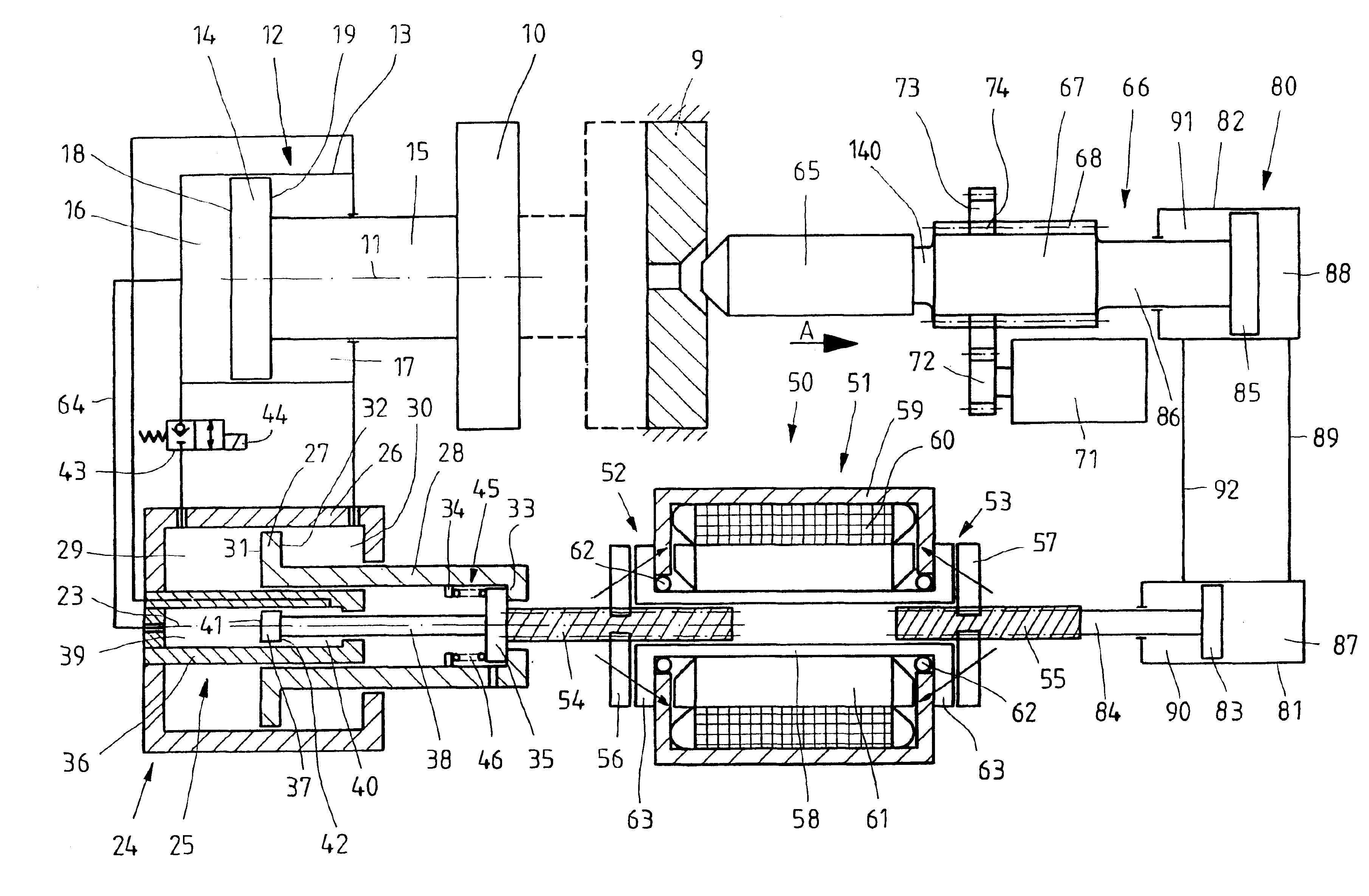
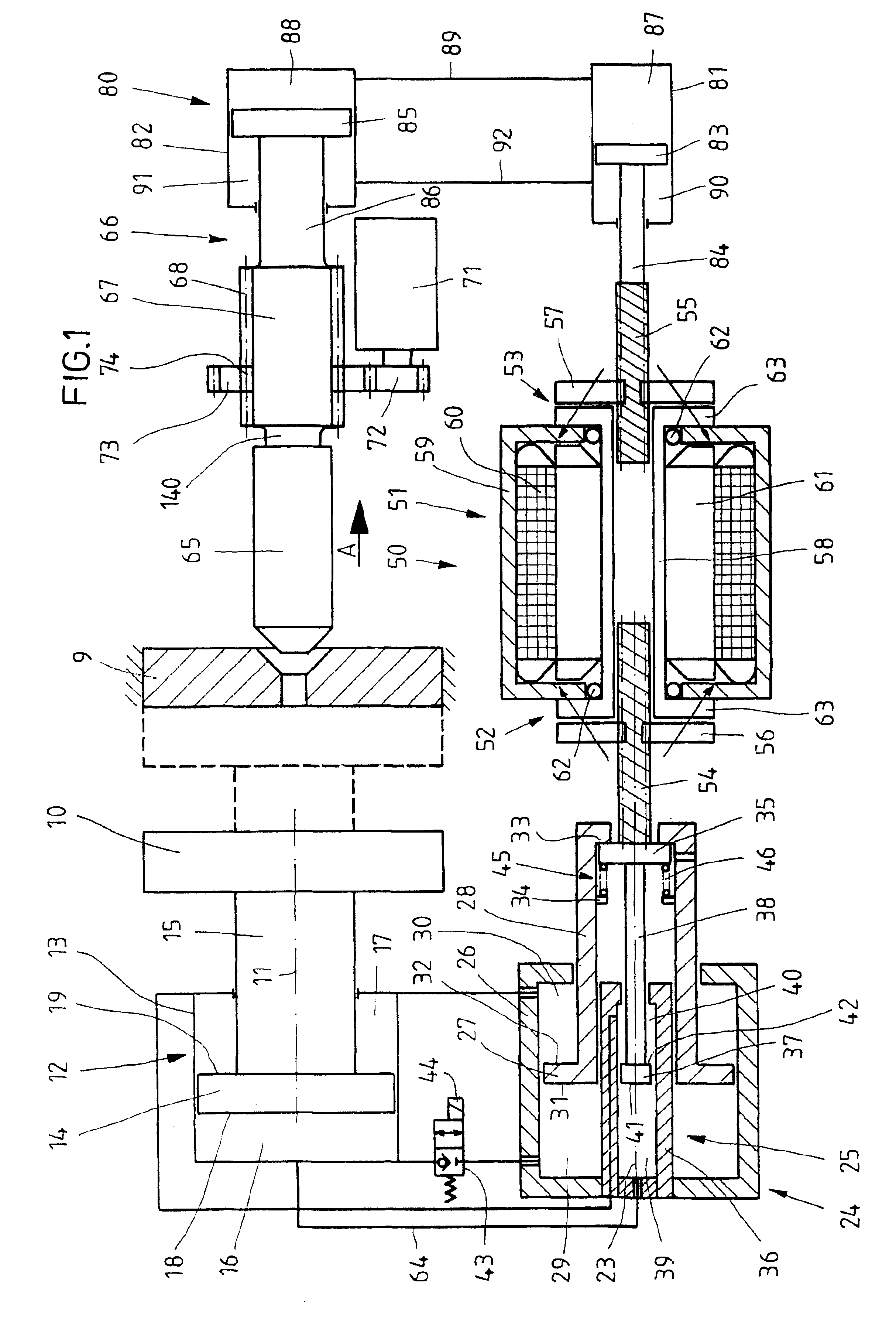
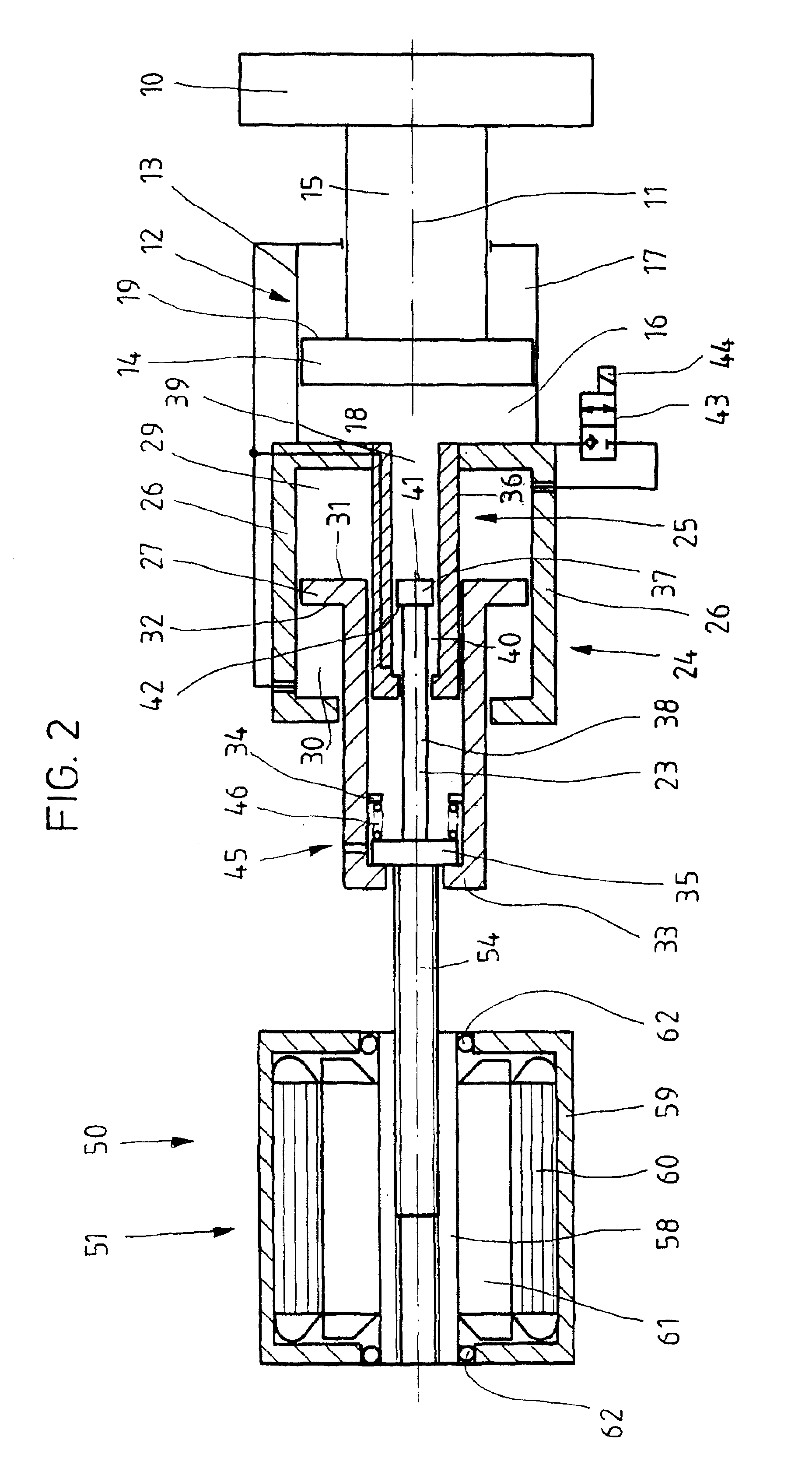
[0039]The supply and the displacement of pressure medium is carried out by and to two further piston-cylinder units, namely a second piston-cylinder unit 24 and a third piston-cylinder unit 25. The latter has a third cylinder housing 36 which is fixed to the frame and whose internal diameter is substantially smaller, for example five times smaller, than the internal diameter of the cylinder housing 13. In the cylinder housing 36, a hydraulic piston 37 constructed as a differential piston can move axially, to which a piston rod 38 projecting out of the cylinder housing 36 in a sealed manner is connected and which divides up the interior of the cylinder housing 36 in a sealed manner into a cylinder chamber 39 with a circularly cylindrically cross section and an annular cylinder chamber 40 located on the side of the piston rod 38. The cylinder chamber 39 is adjoined by the hydraulic piston 37 with an active surface 41 shaped like a circular disk, and the cylinder chamber 40 is adjoined...


PUM

PropertyMeasurementUnit
Pressureaaaaaaaaaa

Abstract

A drive mechanism for an injection molding machine has an output element that is moveable in a straight line and an electric motor drive unit having an electric motor and a piston-cylinder unit which has a first piston-cylinder unit in the force chain between the output element of the electric-motor drive unit and the movable component. A rapid actuating movement is possible and, the action of a high force is also achievable wherein a second piston-cylinder unit and a third piston-cylinder unit. A fluidic connection between the first cylinder chamber and the second cylinder chamber is controllable via a valve. When the valve is open, the second hydraulic piston displaces pressurized liquid from the second cylinder chamber into the first cylinder chamber, to actuate the movable component and, when the valve is closed, the third hydraulic piston displaces pressurized liquid from the third cylinder chamber into the first cylinder chamber to exert a high force on the movable component.

Description

FIELD AND BACKGROUND OF THE INVENTION[0001]The invention relates to a drive mechanism which is intended to be used particularly for the closing unit or the injection unit or the ejector of a plastics injection molding machine having an output element (54) that can be moved in a straight line and an electric-motor drive unit (50) having an electric motor (51), and having at least a first piston-cylinder unit (12), which has a first cylinder housing (13) and first hydraulic piston (14) which, with a first active surface (18, 19), bounds a first cylinder chamber (16, 17) filled with pressurized liquid and lies in the force chain between the output element (54) of the electric-motor drive unit (50) and the movable component (10, 66).[0002]Inside the closing unit of a plastics injection molding machine, the drive mechanism moves the movable mold clamping plate of the machine. A drive mechanism of this type has to satisfy two important different requirements. Firstly, it is to move the mo...

Claims


Application Information

Patent Timeline
IPC IPC(8): B29C45/67B29C45/07F15B3/00B29C45/17B29C45/40B29C45/50B29C45/68B29C45/70B29C45/82
CPCB29C45/07B29C45/4005B29C45/5008B29C45/67B29C45/68B29C45/70B29C2045/506B29C2045/5088B29C2045/685
Inventor DANTLGRABER, JORG
Owner BOSCH REXROTH AG
Why Eureka
Try Eureka