Plasma gas distributor with integral metering and flow passageways

a gas distributor and flow passage technology, applied in plasma welding apparatus, plasma technique, manufacturing tools, etc., can solve the problems of component degradation, electrode and tip wear, and extreme high temperatures and severe conditions, and achieve the effect of prolonging the life of the electrod

Active Publication Date: 2006-10-24
VICTOR EQUIP
View PDF14 Cites 21 Cited by
  • Summary
  • Abstract
  • Description
  • Claims
  • Application Information

AI Technical Summary

Benefits of technology

[0006]In one preferred form, the present invention provides a gas distributor for use in a plasma arc torch that comprises a body defining a proximal end portion and a distal end portion, at least one plasma gas passageway formed in the proximal end portion, a metering passageway formed conjointly with the plasma gas passageway, and at least one helical gas passageway formed along an interior portion of the body. The helical gas passageway is in fluid communication with the plasma gas passageway and the metering passageway, and the combination of the metering passageway and the helical gas passageway functions to reduce the amount of molten Hafnium that is ejected from an electrode when the arc shuts off, thus extending the life of the electrode.
[0007]In another form of the present invention, a plasma arc torch is provided that comprises an electrode, a tip, and a gas distributor disposed between the electrode and the tip. The gas distributor comprises a body defining a proximal end portion and a distal end portion, at least one plasma gas passageway formed in the proximal end portion, at least one metering passageway formed conjointly with the plasma gas passageway, and at least one helical gas passageway formed along an interior portion of the body. The helical gas passageway is in fluid communication with the plasma gas passageway and the metering passageway, and the combination of the metering passageway and the helical gas passageway functions to reduce the amount of molten Hafnium that is ejected from an electrode when the arc shuts off, thus extending the life of the electrode.

Problems solved by technology

During operation of the plasma arc torch, both the electrode and the tip, among other components, are subjected to extremely high temperatures and severe conditions from the high current, gas flow, and the plasma stream, in addition to chemical reactions with different types of gases at high temperatures.
These conditions are especially intense within the plasma arc chamber, and as a result, cause wear of the electrode and the tip over time.
With increased wear, the performance of these components degrades, causing the plasma stream to become less controlled and constricted, which eventually effects cut quality of the plasma arc torch in a negative manner.
During operation however, the Hafnium wears according to several mechanisms depending on the stage of the cutting process.
At plasma arc shut off, a surge of gas within the plasma arc chamber has a tendency to displace the Hafnium, which becomes molten with the extremely high temperatures.
Accordingly, the displacement of molten Hafnium increases wear of the electrode and decreases the usable life of the electrode.
Additionally, Hafnium is a relatively expensive material and thus it is desirable to reduce wear and replacement of the electrodes as much as possible.

Method used


Image

  • Plasma gas distributor with integral metering and flow passageways
  • Plasma gas distributor with integral metering and flow passageways
  • Plasma gas distributor with integral metering and flow passageways

Examples


Embodiment Construction

[0030]The following description of the preferred embodiments is merely exemplary in nature and is in no way intended to limit the invention, its application, or uses.

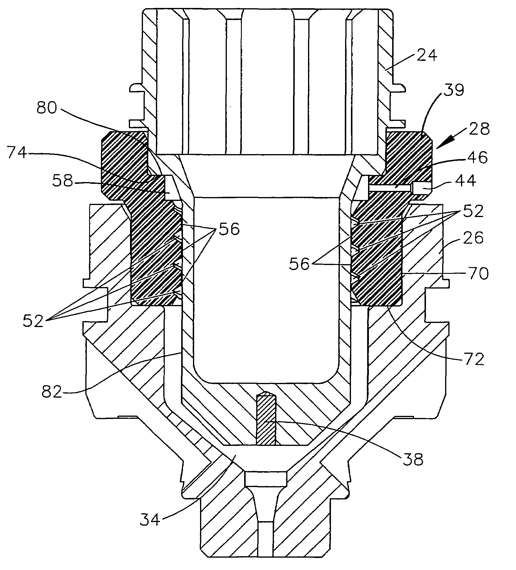
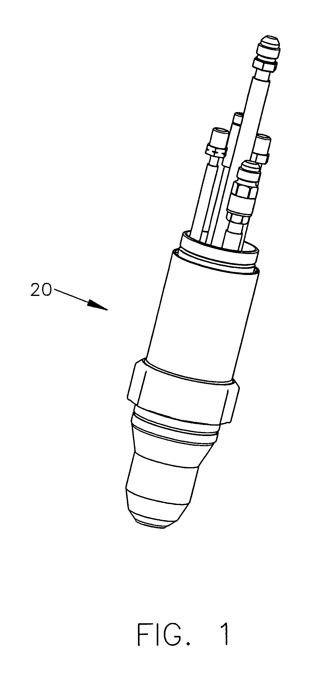
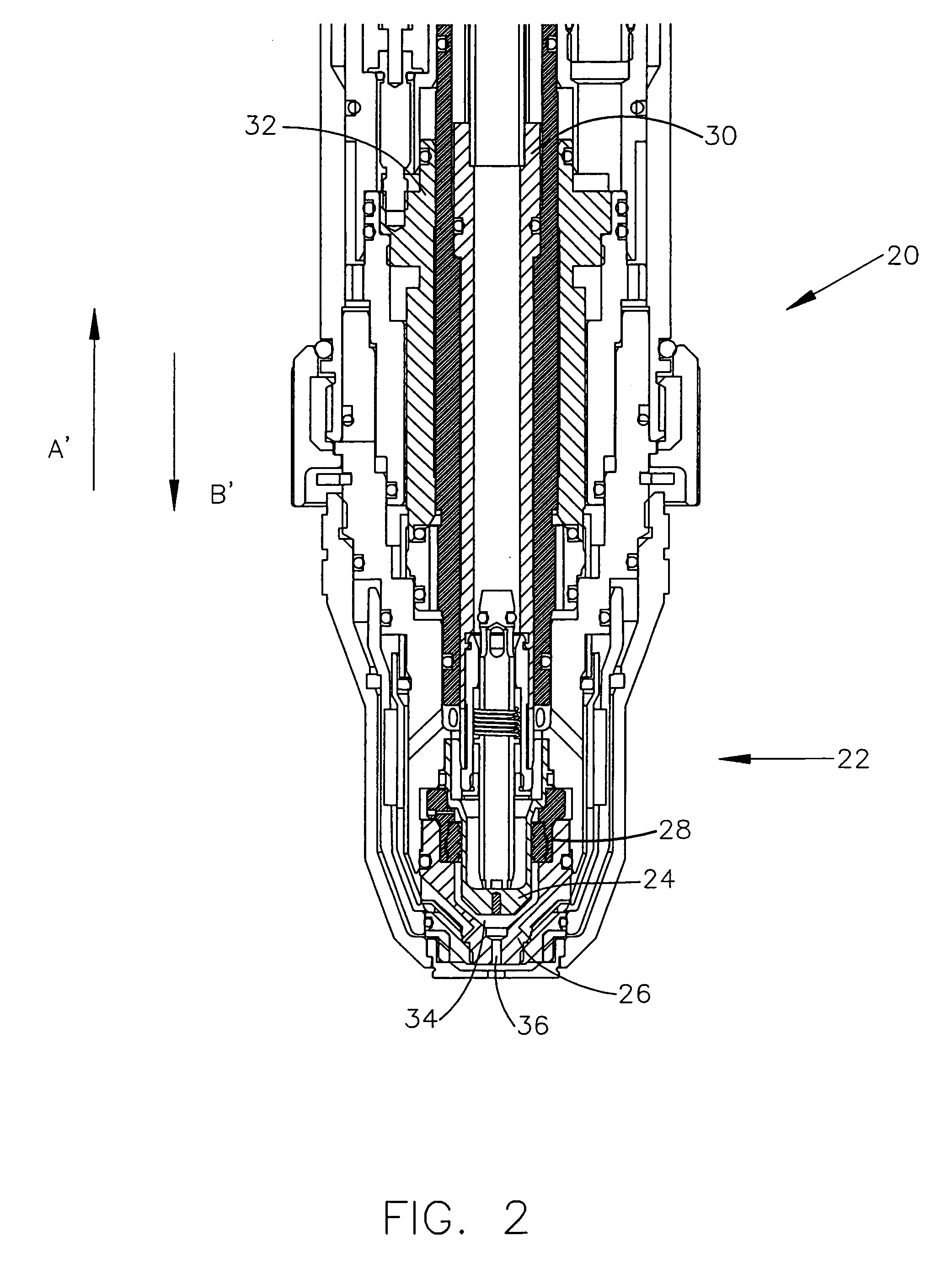
[0031]Referring to FIGS. 1 and 2, a plasma arc torch according to the principles of the present invention is illustrated and generally indicated by reference numeral 20. Although the plasma arc torch 20 as shown is an automated torch, the teachings of the present invention may also applicable to a manual plasma arc torch, with either a contact start such as that shown and described in U.S. Pat. No. 6,903,301 titled “Contact Start Plasma Arc Torch and Method of Initiating a Pilot Arc,” or a high frequency start torch such as that shown and described in U.S. Pat. No. 6,163,008 titled “Plasma Arc Torch,” both of which are commonly owned with the present application and the contents of which are incorporated by reference herein in their entirety.

[0032]As used herein, a plasma arc torch, whether operated manually or automate...


PUM

PropertyMeasurementUnit
surface areaaaaaaaaaaa
electrically insulatingaaaaaaaaaa
sizeaaaaaaaaaa

Abstract

A gas distributor for use in a plasma arc torch is provided that has at least one plasma gas passageway formed conjointly with a metering passageway, and at least one helical gas passageway formed along an interior portion of the gas distributor, wherein the helical gas passageway is in fluid communication with the plasma gas passageway and the metering passageway. The combination of the metering passageway and the helical gas passageway provides for a metered flow rate and a controlled swirling flow of plasma gas within the plasma arc chamber, respectively, which functions to reduce the amount of molten emissive insert that is ejected from within an electrode at arc shut off, thereby resulting in an increased life of the consumable electrode.

Description

FIELD OF THE INVENTION[0001]The present invention relates generally to plasma arc torches and more particularly to devices and methods to improve the life of consumable components that operate within a plasma arc torch.BACKGROUND OF THE INVENTION[0002]Plasma arc torches, also known as electric arc torches, are commonly used for cutting, marking, gouging, and welding metal workpieces by directing a high energy plasma stream consisting of ionized gas particles toward the workpiece. In a typical plasma arc torch, the gas to be ionized is supplied to a distal end of the torch and flows past an electrode before exiting through an orifice in the tip, or nozzle, of the plasma arc torch. The electrode has a relatively negative potential and operates as a cathode. Conversely, the torch tip constitutes a relatively positive potential and operates as an anode. Further, the electrode is in a spaced relationship with the tip, thereby creating a gap, at the distal end of the torch. In operation, ...

Claims


Application Information

Patent Timeline
Patent Type & Authority Patents(United States)
IPC IPC(8): B23K10/00
CPCH05H1/34H05H2001/3468H05H1/3468
Inventor RENAULT, THIERRY R.HUSSARY, NAKHLEH A.MACKENZIE, DARRIN H.CONWAY, CHRISTOPHER J.HORNER-RICHARDSON, KEVIN D.
Owner VICTOR EQUIP
Why Eureka
Try Eureka