
Voltage control circuit for common mode voltage and method for controlling the same

a voltage control circuit and common mode technology, applied in the direction of dc-amplifiers with dc-coupled stages, differential amplifiers, semiconductor devices/discharge tubes, etc., can solve the problem of oscillation phenomenon, inability to make the setting error of the common mode voltage on the output side to be a desired value or less, and difficulty in keeping a phase margin or gain margin for the control signal loop. achieve the effect of effective control

Inactive Publication Date: 2006-10-24
RENESAS ELECTRONICS CORP
View PDF12 Cites 6 Cited by
  • Summary
  • Abstract
  • Description
  • Claims
  • Application Information

AI Technical Summary

Benefits of technology

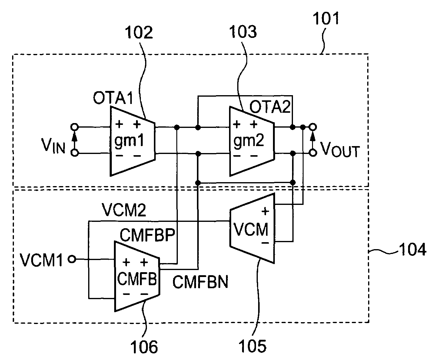
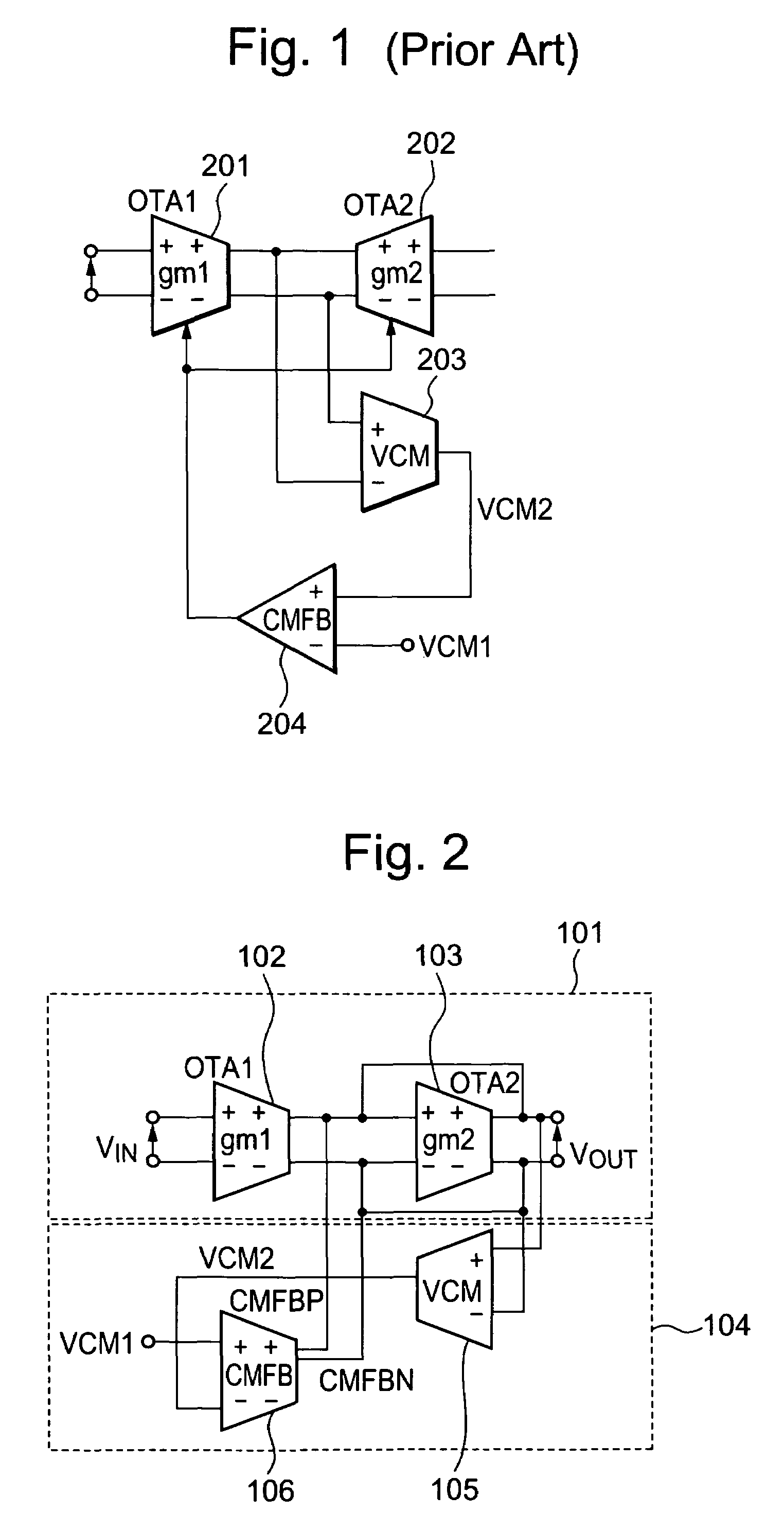
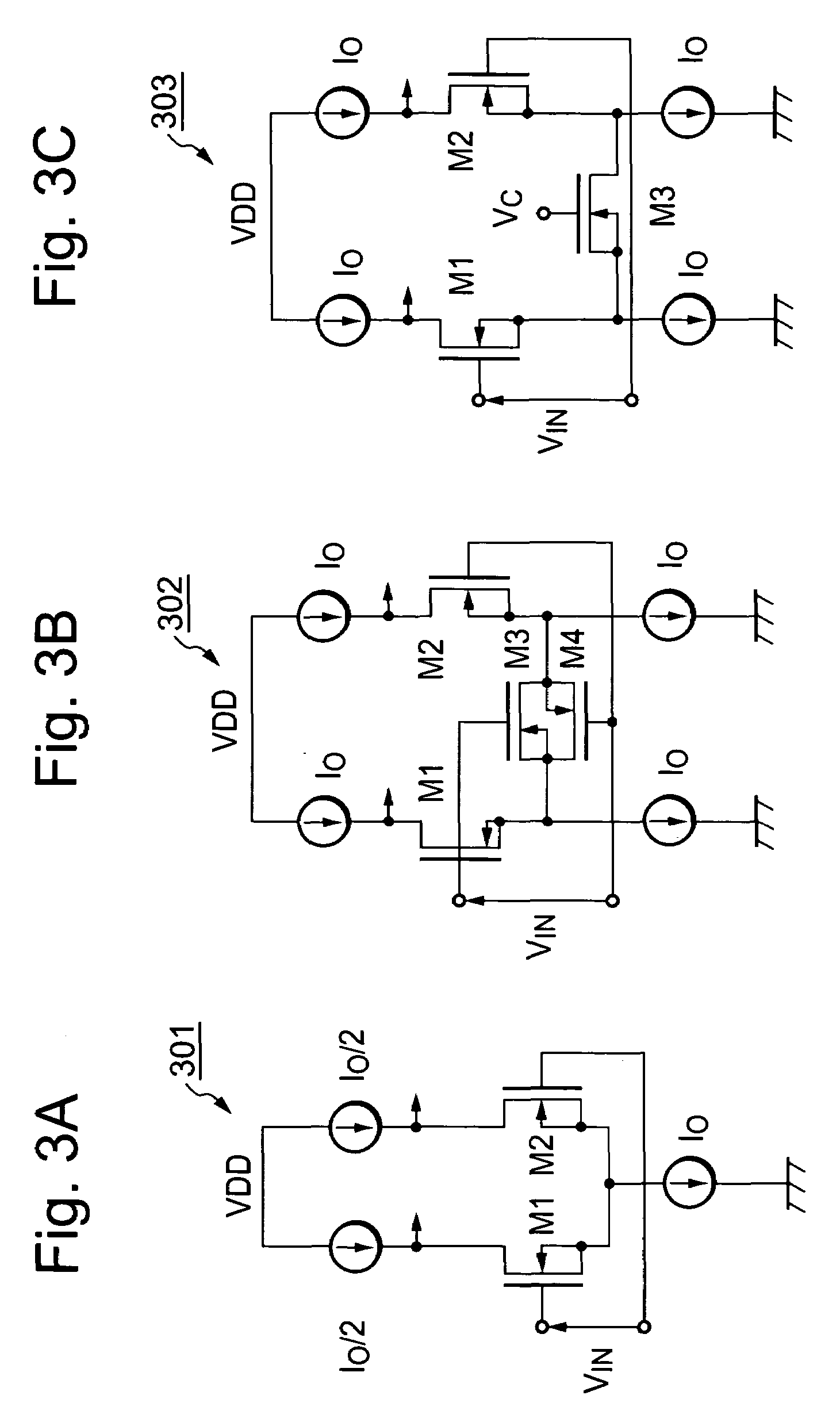
[0015]A voltage control circuit for a common mode voltage according to a first aspect of the present invention includes: a detection circuit for detecting a common mode voltage from differential output terminals of a differential circuit, and outputting a detected voltage based on the common mode voltage of the differential output; and a transconductance circuit for inputting the detected voltage and a first reference voltage, and inputting / outputting currents based on a voltage difference between the detected voltage and the first reference voltage. The outputted currents from the operational transconductance amplifier are inputted to the differential output of the differential output circuit. The voltage control circuit for the common mode voltage according to the first aspect of the present invention can effectively control the common mode voltage of the differential output with the above configuration.
[0016]A method for controlling a common mode voltage of differential output according to a second aspect of the present invention includes the steps of: detecting a common mode voltage of the differential output terminals; outputting a detected voltage based on the common mode output voltage; and outputting currents in accordance with a voltage difference between the detected voltage and a first reference voltage. With this configuration, the common mode voltage of the differential output can be effectively controlled.

Problems solved by technology

Therefore, with regard to the control signal loop, influence of the ordinary signal loop appears therein, which makes it difficult to keep a phase margin or a gain margin for the control signal loop.
However, when the gain is set higher, circuit operation becomes unstable because the phase margin for the control signal loop becomes smaller, thereby causing a problem that an oscillation phenomenon appears in the control signal loop.
On the other hand, when the gain of the control signal loop is set lower so that the circuit operates stably, the setting error of the common mode voltage on an output side cannot be made to be a desired value or less.
Therefore, an influence of the input signal appears in the control signal loop, it makes the control signal loop very difficult to secure the phase margin or the gain margin.
Moreover, when the gain of the control signal loop is reduced in order to secure the phase margin of the control signal loop, the setting error becomes large.
Therefore, it is difficult to reduce current consumption of the circuit.

Method used


Image

  • Voltage control circuit for common mode voltage and method for controlling the same
  • Voltage control circuit for common mode voltage and method for controlling the same
  • Voltage control circuit for common mode voltage and method for controlling the same

Examples


Embodiment Construction

[0024]The invention will be now described herein with reference to illustrative embodiment. Those skilled in the art will recognize that many alternative embodiments can be accomplished using the teachings of the present invention and that the invention is not limited to the embodiment illustrated for an explanatory purpose.

[0025]First, an example of a semiconductor integrated circuit device of the present invention will be described in detail with reference to a drawing. In the drawing, reference codes are the same as FIG. 1 that denotes the same elements, and an explanation thereof will be omitted as appropriate in the detailed description below.

[0026]Second, an applicable embodiment of the present invention will be described. The description will be given of an illustrative purpose only of the embodiment of the present invention, and thus the present invention is not limited to the embodiment below. Some description may be omitted and simplified as appropriate to clarify the expl...


PUM


Abstract

A common mode voltage detection circuit 105 detects a common mode voltage VCM from differential output terminals of a differential output circuit 101. The common mode voltage detection circuit outputs a detected voltage VCM2 in accordance with the common mode voltage VCM. An OTA 106 in the common mode feedback loop inputs or outputs multiple currents of the same phase in accordance with a voltage difference between a reference voltage VCM1 and the detected voltage VCM2. The respective multiple currents of the same phase are inputted / outputted to / from the two respective terminals of the differential output terminals. The common mode voltage can be reduced by flowing the currents into the differential output terminals, and can be increased by leading the currents from the differential output terminals. Thus, a phase margin or a gain margin of a control signal loop can be secured even with low current consumption, thereby realizing stable operation of the circuit.

Description

BACKGROUND OF THE INVENTION[0001]1. Field of the Invention[0002]The present invention relates to a voltage control circuit for a common mode voltage and a method for controlling the same. More specifically, the present invention relates to a voltage control circuit of a common mode voltage for an operational amplifier or an operational transconductance amplifier (hereinafter abbreviated as OTA) which has differential outputs and controls the common mode voltage of the differential outputs, and to a method for controlling the common mode voltage.[0003]2. Description of the Related Art[0004]As an integration of semiconductor integrated circuits becomes higher and digital technologies develop more advancement in recent years, circuits with digital and analog circuits formed in a large scaled integrated (LSI) chip have been mounted in many consumer products.[0005]Moreover, in the field of analog circuits, circuits such as operational amplifiers or OTAs having differential outputs are we...

Claims


Application Information

Patent Timeline
Patent Type & Authority Patents(United States)
IPC IPC(8): H03F3/45H03F3/68
CPCH03F3/45941H03F2203/45406
Inventor KIMURA, KATSUJI
Owner RENESAS ELECTRONICS CORP
Learn More