Digital phase locked loop with selectable normal or fast-locking capability

a digital phase lock and capability technology, applied in digital transmission, electrical equipment, automatic control, etc., can solve the problems of inability to meet the requirements of two major fast-locking modes, inability to align the final output clock to the active input reference, and inability to ensure the stability of the holdover, so as to prevent the amplification of sampling error noise, fast alignment, and quick buildup

Active Publication Date: 2006-10-24
ZARLINK SEMICON LTD
View PDF7 Cites 53 Cited by
  • Summary
  • Abstract
  • Description
  • Claims
  • Application Information

AI Technical Summary

Benefits of technology

[0008]This invention resolves the issues regarding alignment of the output clock to the active input reference clock and holdover frequency stability in fast-locking mode. With this invention, both issues can be achieved in a very short period of time, called fast-locking time. The fast-locking time depends on the chosen DPLL filter response.
[0015]According to another aspect of the invention there is provided a method of controlling a digital phase locked loop wherein in a fast locking mode a loop filter applies a weighting factor to the proportional value of phase error (P-value), representing the phase difference between the an output clock and an active input reference clock, prior to passing it to an integrator, in order to achieve fast alignment of the output clock to the active input reference clock in a fast locking mode and fast achievement of stable holdover frequency in a holdover mode.

Problems solved by technology

However, previous implementations fail to meet two major fast-locking mode requirements.
Firstly, the holdover frequency could be far from the guaranteed holdover stability if holdover mode was entered shortly after the fast-locking time passes.
Secondly, the final output clock was not aligned to the active input reference after this short, fast-locking time.
This misalignment could cause failures in a system where that DPLL was used as clock synchronizer, especially in systems with high clock and data rate, comparable to the sampling error.

Method used


Image

  • Digital phase locked loop with selectable normal or fast-locking capability
  • Digital phase locked loop with selectable normal or fast-locking capability
  • Digital phase locked loop with selectable normal or fast-locking capability

Examples


Embodiment Construction

[0022]The DPLL modules that do not directly contain the invention, but are important for understanding of the invention, will be explained in lesser detail. The modules of the DPLL containing the invention will be explained in greater detail.

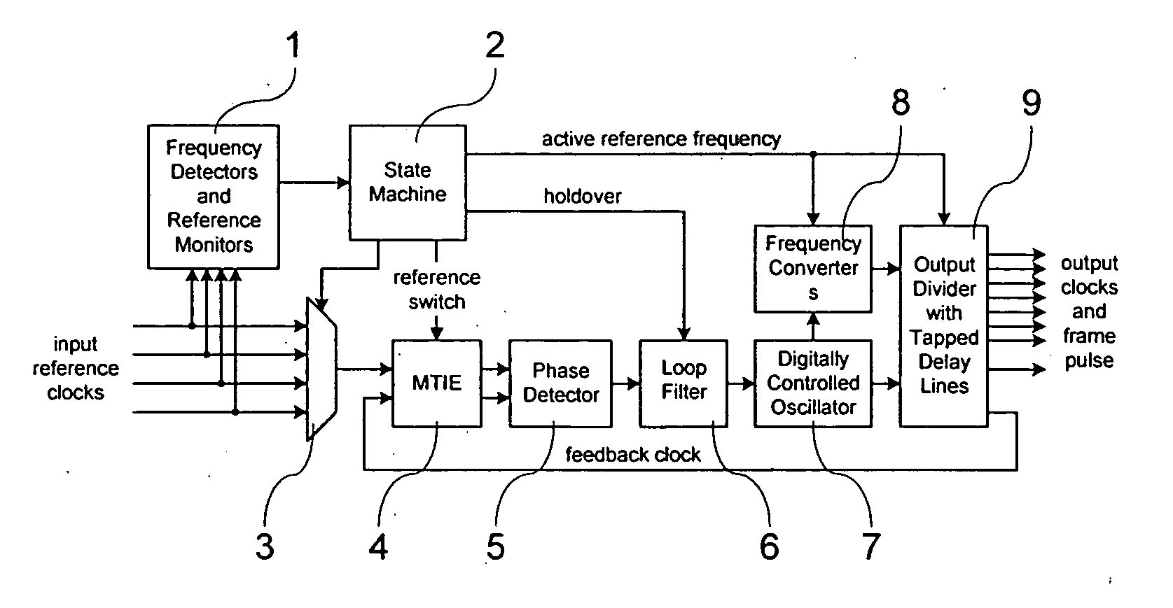
[0023]Referring to FIG. 1, the DPLL circuit that is capable of providing a complete set of both normal and fast-locking functionality consists of the following modules: four Frequency Detectors and Reference Monitors 1, State Machine 2, Input Reference Multiplexer 3, Maximum Time Interval Error (MTIE) module 4, Phase Detector 5, Loop Filter 6, Digitally Controlled Oscillator (DCO) 7, two Frequency Converters 8 and Output Divider with three Tapped Delay Lines (TDLs) 9.

[0024]The Frequency Detectors 1 determine the frequency of the incoming reference clocks and send coded binary value to the State Machine 2.

[0025]The Reference Monitor modules 1 monitor the existence and frequency offset of the input reference clocks and notify the State Machine mod...


PUM


Abstract

A digital phase locked loop with fast locking capability includes a digitally controlled oscillator for producing an output signal phase locked to an input reference clock, a phase detector for measuring the phase difference between said input reference clock and a feedback clock, and a loop filter for producing a control signal for the digitally controlled oscillator The loop filter includes a proportional circuit for developing a first signal proportional to said phase difference, an integrator for developing a second integrated signal from said first signal, an adder for adding said first and second signals to develop said control signal, and a weighting circuit, preferably a linear multiplier, for selectively adding extra weight to the first signal at an input to the integrator to shorten the locking time of the phase locked loop in a fast locking mode and to rapidly achieve a stable frequency in holdover mode.

Description

FIELD OF THE INVENTION[0001]This invention relates to the field of digital signal synchronization. In particular, the invention relates to a digital phase locked loop (DPLL) with selectable fast-locking capability.BACKGROUND OF THE INVENTION[0002]In digital communications, where signal synchronization devices are used, there are often requirements for DPLLs that can meet certain standards which define their filter response, and also have the capability of fast locking to a reference signal. Fast locking is especially desired upon power-up and during manual clock reference rearrangement. The normal locking time for a DPLL is inversely proportional to its filter response, so fast locking is very useful when standards prescribe a slow response (small corner frequency).[0003]In prior art DPLL implementations (e.g. the embedded DPLL in Zarlink's MT90866 H.110 Compatible Digital Switch), some instances of fast-locking have been achieved by pushing the DPLL corner frequency to the higher f...

Claims


Application Information

Patent Timeline
Patent Type & Authority Patents(United States)
IPC IPC(8): H03L7/00H03L7/08H03L7/093H03L7/099H03L7/107H03L7/14H04L7/00
CPCH03L7/093H03L7/0991H03L7/107H03L7/1075H03L7/143H03L7/146H04J3/0688
Inventor MITRIC, KRSTE
Owner ZARLINK SEMICON LTD
Why Eureka
Try Eureka