Magneto-optical recording medium and method for producing the same

a magnetic recording medium and optical recording technology, applied in the field of magnetic recording medium, can solve the problems of inability to completely conduct magnetic separation, and difficulty in reproducing information from individual recording bits separately, and achieve satisfactory reproduction characteristics, influence of leakage magnetic field on the displacement of a domain wall

Inactive Publication Date: 2006-10-24
PANASONIC CORP +1
View PDF15 Cites 0 Cited by
  • Summary
  • Abstract
  • Description
  • Claims
  • Application Information

AI Technical Summary

Benefits of technology

[0020]According to the production method of the present invention, the perpendicular magnetic anisotropy between recording tracks is reduced to weaken a magnetic interaction between the recording track and the land. Simultaneously, minute micro-domains can be formed. If this production method is used, the influence of a leakage magnetic field on the displacement of a domain wall in a magneto-optical recording medium is alleviated, and the medium can be initialized.
[0021]The above-mentioned magneto-optical recording medium of the present invention is a novel one provided by the above-mentioned production method, in which satisfactory reproduction characteristics can be obtained even from a signal recorded in a state as it is.

Problems solved by technology

This is caused as follows: an adjacent recording bit enters the diameter of a light beam focused onto an intended recording bit, which makes it difficult to reproduce information from individual recording bits separately.
As a result, magnetic separation cannot be conducted completely, which inhibits the displacement of a domain wall.

Method used


Image

  • Magneto-optical recording medium and method for producing the same
  • Magneto-optical recording medium and method for producing the same
  • Magneto-optical recording medium and method for producing the same

Examples


embodiment 1

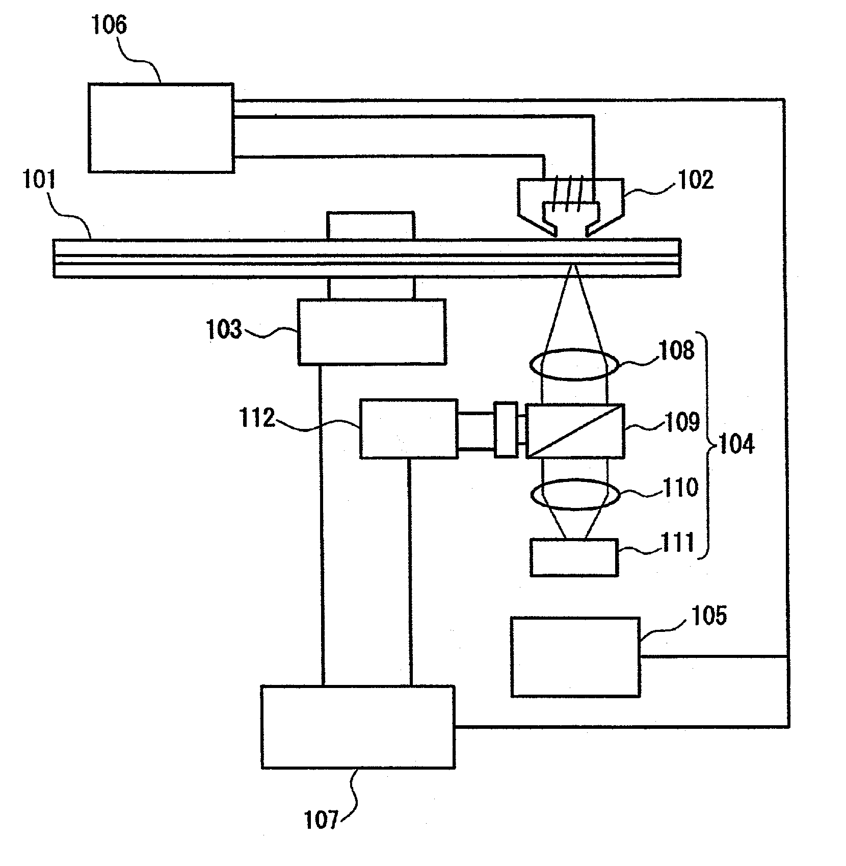
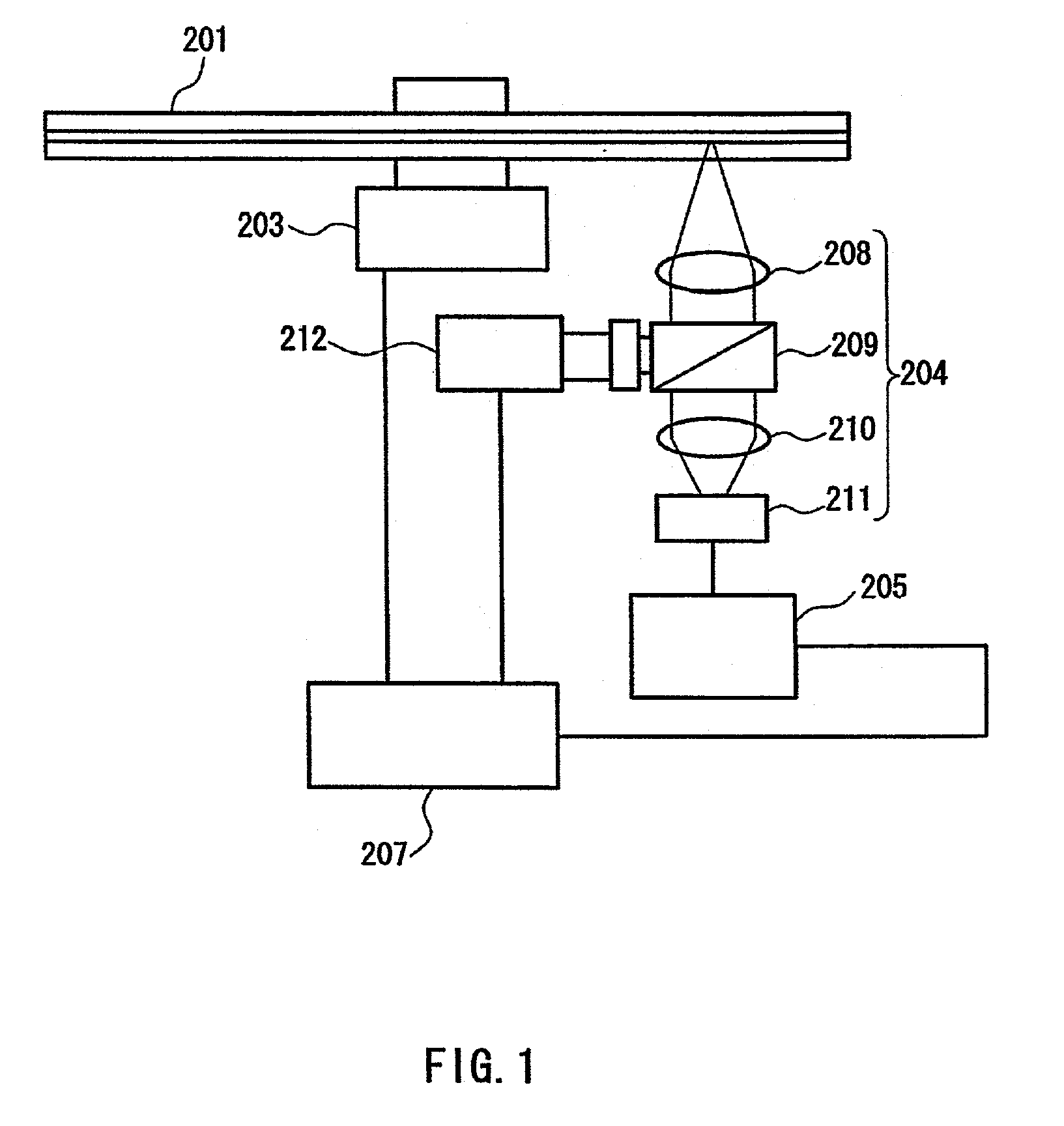
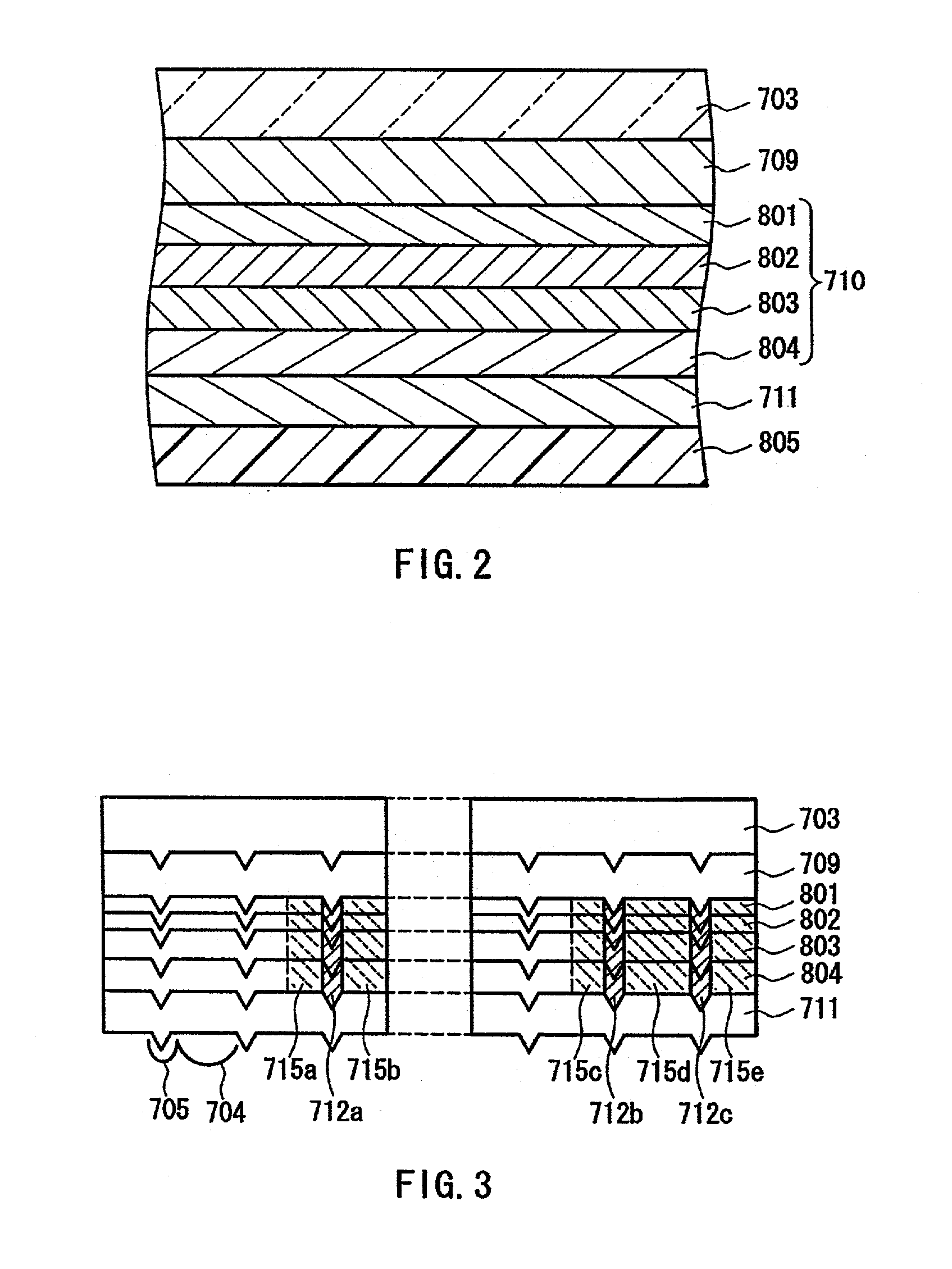
[0044]Referring to FIGS. 2 to 4, an example of a method for producing a magneto-optical disk will be described.

[0045]Reference numeral 703 denotes a disk-shaped substrate, which can be made of polycarbonate, glass, or the like. Herein, the substrate 703 was obtained by injection-molding a polycarbonate material so that first wobble pits 706, second wobble pits 707, and address pits 708 were formed in a pit region 701 for the purpose of using a sampling servo system for tracking during recording / reproducing of information, and guide grooves (groove width: 0.45 μm, land width: 0.19 μm, depth: 50 nm) were formed in a groove region 702 for the purpose of conducting tracking during annealing. In this substrate, the track pitch becomes 0.64 μm. A first dielectric layer 709 and a second dielectric layer 711 can be made of, for example, a dielectric material such as Si3N4, AlN, SiO2, SiO, ZnS, MgF2, and Ta2O5 (each material is not limited to a composition determined by a stoichiometric rati...

embodiment 2

[0063]FIG. 6 shows a film configuration of a magneto-optical disk of Embodiment 2, and FIG. 7 is a partially cut-away perspective view thereof. Reference numeral 403 denotes a disk-shaped substrate, which can be made of polycarbonate, glass, or the like. Herein, a substrate was obtained by injection-molding a polycarbonate material so that first wobble pits 406, second wobble pits 407, and address pits 408 were formed in a pit region 401 for the purpose of using a sampling servo system for tracking during recording / reproducing of information, and guide grooves (groove width: 0.5 μm, land width: 0.15 μm, depth: 55 nm) were formed in a groove region (data region)402 for the purpose of conducting tracking during annealing. A first dielectric layer 409 and a second dielectric layer 411 can be made of the same dielectric materials as the above.

[0064]Hereinafter, an example of a method for forming each layer will be described.

[0065]Respective targets: Si doped with B, GdFeCo, TbFe, Fe, Co...

embodiment 3

[0072]FIG. 8A is an enlarged cross-sectional view taken along a diameter direction, showing a configuration of a recording domain of a magneto-optical disk after annealing in the present embodiment, and FIG. 8B is an enlarged plan view thereof. Herein, a substrate 403 was obtained by injection-molding a polycarbonate material so that guide grooves (groove width: 0.4 μm, land width: 0.2 μm, depth: 75 nm) were formed in a groove region 402. On the substrate 403, the following layers were formed successively in the same way as the above. First, a SiN layer (first dielectric layer) 409 was formed in a thickness of 80 nm. Then, GdFeCo (Curie temperature TC1=290° C.) was formed in a thickness of 30 nm as a first magnetic layer (reproducing layer) 501. TbFeCo (TC2=180°) was formed in a thickness of 5 nm as a second magnetic layer (control layer) 502. TbFeAl (TC3=160° C.) was formed in a thickness of 10 nm as a third magnetic layer (intermediate layer) 503. TbFeCo (TC4=400° C.) was formed a...


PUM

PropertyMeasurementUnit
wavelengthaaaaaaaaaa
diameteraaaaaaaaaa
diameteraaaaaaaaaa

Abstract

According to the present invention, a light beam is radiated to an area between recording tracks while the intensity of a magnetic field from the outside to a magneto-optical recording medium is suppressed to 50 Oe or less, whereby magnetic anisotropy formed between the recording tracks is set to be lower than that of the magnetic layer on the recording tracks, and micro-domains, for example, having a diameter smaller than a half-width of a light beam for reproduction in a film surface direction are formed on recording tracks. Because of this method, the influence of a leakage magnetic field in the magneto-optical recording medium adopting a DWDD reproducing system is alleviated.

Description

BACKGROUND OF THE INVENTION[0001]1. Field of the Invention[0002]The present invention relates to a magneto-optical recording medium used for recording or reproducing information, a method for producing the same, and an apparatus for producing the same.[0003]2. Description of the Related Art[0004]As a repeatedly rewritable recording medium having a high density, a magneto-optical recording medium and a recording / reproducing apparatus for recording a minute domain onto a magnetic thin film with thermal energy of laser light, and reproducing a signal using a magneto-optical effect are being developed actively. In such a magneto-optical recording medium, when the diameter and interval of recording bits (domains for recording) become smaller with respect to the diameter of a light beam focused onto the medium, reproduction characteristics are degraded. This is caused as follows: an adjacent recording bit enters the diameter of a light beam focused onto an intended recording bit, which ma...

Claims


Application Information

Patent Timeline
Patent Type & Authority Patents(United States)
IPC IPC(8): G11B11/10G11B11/105G11B11/00
CPCG11B11/10528G11B11/10582G11B11/10584
Inventor MURAKAMI, MOTOYOSHIBIRUKAWA, MASAHIROSHIRATORI, TSUTOMUMIYAOKA, YASUYUKI
Owner PANASONIC CORP
Why Eureka
Try Eureka