Exhaust gas purifying apparatus of internal combustion engine

a technology of exhaust gas purification apparatus and internal combustion engine, which is applied in the direction of machines/engines, electrical control, separation processes, etc., can solve the problems of undetectable oxidation, difficult to sufficiently reduce undetectable nox in exhaust gas, so as to achieve advantageously reduce the o2 storage ability of light-off catalys

Inactive Publication Date: 2006-10-31
MITSUBISHI MOTORS CORP
View PDF37 Cites 20 Cited by
  • Summary
  • Abstract
  • Description
  • Claims
  • Application Information

AI Technical Summary

Benefits of technology

[0024]The light-off catalyst is preferably constructed such that the amount of oxygen adsorbed on the catalyst is not greater than about 150 cc per one-liter volume of the catalyst when measured according to an oxygen pulse method. Thus, the O2 storage ability of the light-off c...

Problems solved by technology

In this type of internal combustion engine, it is difficult to reduce NOx in exhaust gases during the lean burn operation, by using a conventional three-way catalyst having a function of reducing CO, HC, and NOx in exhaust gases when the engine is operating at around the stoichiometric air/fuel ratio.
While NOx in the exhaust gas can be surely reduced by the lean NOx catalyst during the lean burn operation, it is still difficult to sufficiently reduce HC in the exhaust gas when the engine starts operating in a cold state, for example, only by using the lean NOx catalyst as described above.
The use of both the lean NOx catalyst and the light-off catalyst as disclosed in the above first and second publications, however, suffers from a problem as follows: since the light-off catalyst has an O2 storage function, CO that is needed for releasing adsorbed NOx from the lean NOx catalyst in a reducing atmosphere is undesirably oxidized by the light-off catalyst, and a sufficient amount of CO cannot be supplied to the lean NOx catalyst.
Thus, the NOx adsorbed on the lean NOx catalyst may not be sufficiently released from the catalyst because of the oxidation of CO by the light-off catalyst.
Since CO supplied by the recovery control is oxidized and consumed...

Method used


Image

  • Exhaust gas purifying apparatus of internal combustion engine
  • Exhaust gas purifying apparatus of internal combustion engine
  • Exhaust gas purifying apparatus of internal combustion engine

Examples


Embodiment Construction

)

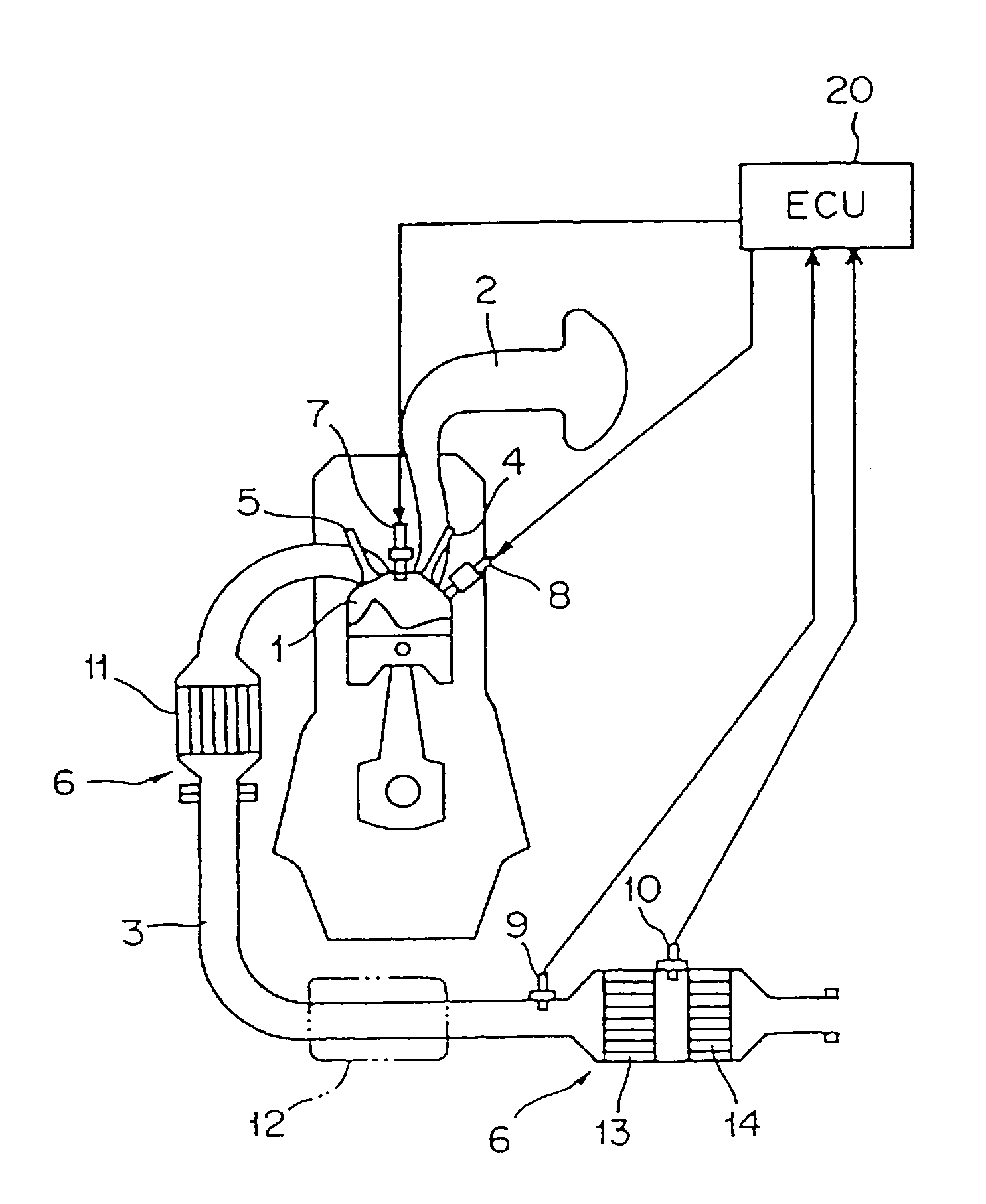
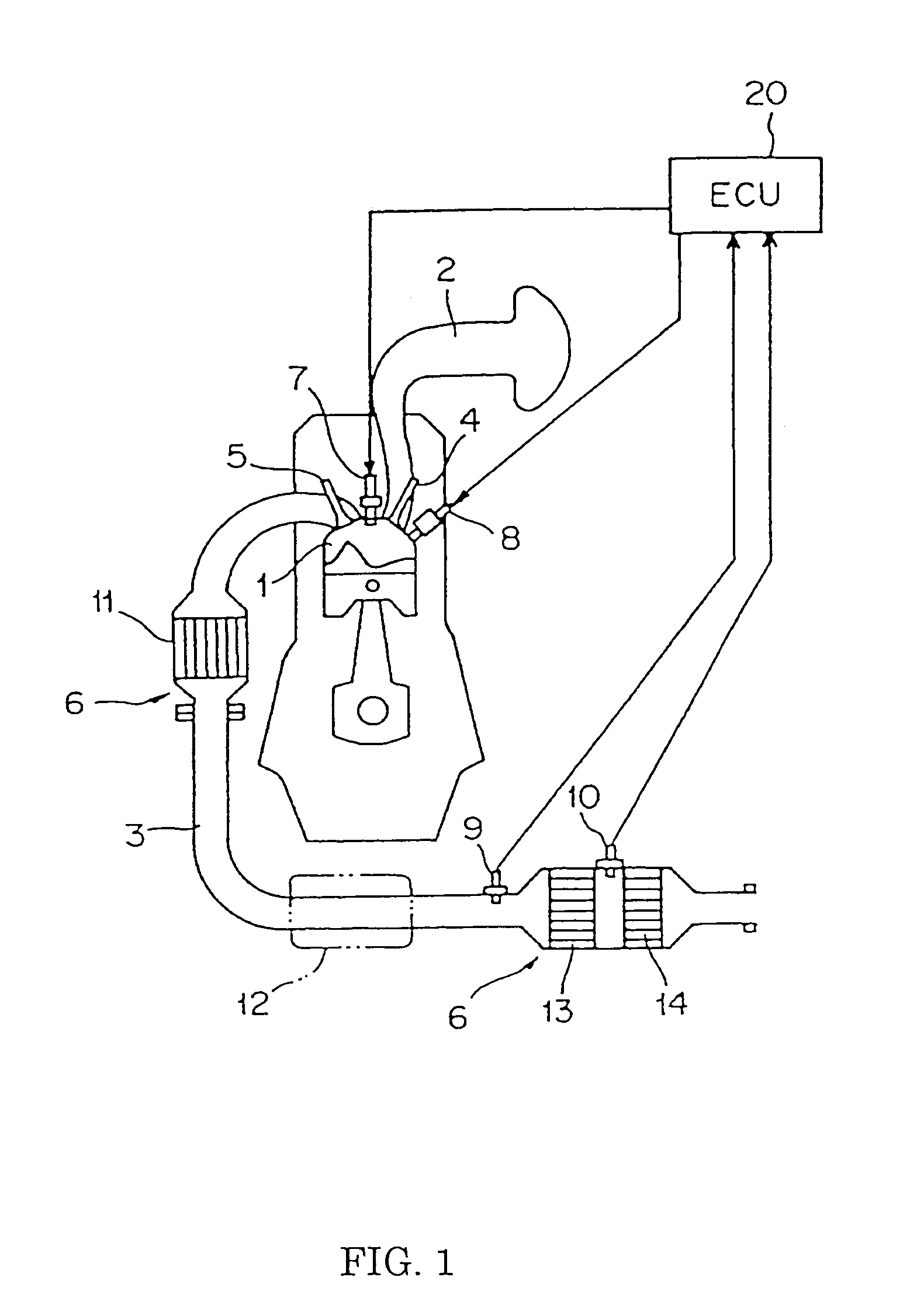
[0038]Referring to FIG. 1 through FIG. 8, an exhaust gas purifying apparatus of an internal combustion engine according to one embodiment of the present invention will be described in detail.

[0039]Initially, the internal combustion engine equipped with the exhaust gas purifying apparatus of the present embodiment will be described. The internal combustion engine, which is constructed as shown in FIG. 1, is a spark ignition type four-cycle engine that operates on the four-stroke cycle consisting of suction stroke, compression stroke, combustion / expansion stroke, and exhaust stroke. Also, the internal combustion engine of the present embodiment is constructed as an in-cylinder injection type engine in which the fuel is directly injected into a combustion chamber 1.

[0040]An intake passage 2 and an exhaust passage 3 are connected to the combustion chamber 1 so that these passages 2, 3 may be in fluid communication with the chamber 1. Also, an intake valve 4 is provided for controlling ...


PUM

PropertyMeasurementUnit
Volumeaaaaaaaaaa
Temperatureaaaaaaaaaa
Concentrationaaaaaaaaaa

Abstract

An exhaust gas purifying apparatus of an internal combustion engine is provided which includes: exhaust gas purifying means, provided in an exhaust passage of the engine, for adsorbing NOx in an exhaust gas when the air-fuel ratio of the exhaust gas is lean. The exhaust gas apparatus releases or reduces the adsorbed NOx when the oxygen concentration of the exhaust gas is reduced. A light-off catalyst is provided upstream of the exhaust gas purifying apparatus in the exhaust passage, which has a lower O2 storage capability than the exhaust gas purifying apparatus. There is a control device for controlling the air-fuel ratio of the exhaust gas so that an atmosphere having a reduced oxygen concentration is produced around the exhaust gas purifying apparatus when the NOx conversion efficiency of the exhaust gas purifying apparatus is decreased.

Description

FIELD OF THE INVENTION[0001]The present invention relates to an exhaust gas purifying apparatus of an internal combustion engine, and in particular to such an exhaust gas purifying apparatus that is able to highly and efficiently reduce harmful components, particularly NOx (nitrogen oxides), contained in exhaust gases, for the internal combustion engine capable of operating with a fuel-lean air / fuel mixture.BACKGROUND OF THE INVENTION[0002]In recent years, internal combustion engines, capable of operating in a lean burn mode with a fuel-lean mixture, have been developed to achieve further improved fuel economy. In this type of internal combustion engine, it is difficult to reduce NOx in exhaust gases during the lean burn operation, by using a conventional three-way catalyst having a function of reducing CO, HC, and NOx in exhaust gases when the engine is operating at around the stoichiometric air / fuel ratio.[0003]In view of the above problem, a new type of catalyst (called adsorptio...

Claims


Application Information

Patent Timeline
IPC IPC(8): F01N3/00B01D53/94F01N3/08F01N3/20F01N13/02F02D41/02F02D41/14F02D41/40
CPCB01D53/9422B01D53/9477B01D53/949B01D53/9495F01N3/0842F01N3/20F02D41/0235F02D41/0275F02D41/028F02D41/146F02D41/405F01N13/0097F01N13/009B01D53/945B01D2255/1021B01D2255/2022B01D2255/2027B01D2255/2042F01N2250/12F01N2430/06F01N2570/04F01N2570/16F02D2200/0811F02D2200/0816Y02T10/44Y02T10/22Y02T10/12Y02T10/40
Inventor KANEKO, KATSUNORIKOGA, KAZUOANDO, HIROMITSU
Owner MITSUBISHI MOTORS CORP
Why Eureka
Try Eureka