
Method of forming polarized or photochromic lenses by fusing polycarbonate with other plastic materials

a technology of polycarbonate and plastic materials, applied in the field of forming polarized or photochromic lenses by fusing polycarbonate with other plastic materials, can solve the problems of large amount of light transmitted, easy scratching, and relatively unstable optic curve, and achieve the effect of less inner stress and improved optical quality

Active Publication Date: 2006-10-31
POLYLITE TAIWAN
View PDF27 Cites 20 Cited by
  • Summary
  • Abstract
  • Description
  • Claims
  • Application Information

AI Technical Summary

Benefits of technology

"The present invention provides a method for surface treatment to bond different thermoplastic and thermosetting plastic materials interfaces, particularly for producing polarized and photochromic ophthalmic lenses. The method involves applying an electrical discharge to a substrate surface, applying an adhesive to the substrate, and then polymerizing a monomer. The resulting plastic material is then bonded to a thermosetting plastic lens using a special treatment to discharge the surface of the PVA polarized film and apply glue and cure with photo-chemical technology. The resulting lens unit is a single solid lens that provides optic quality functionality. The invention also provides a lens produced by the abovestated method and various design lenses, such as single vision lens, bifocal lens, multi-focal lens, and progressive lens. The hard coating is applied on both concave and convex side of the polycarbonate polarized and / or photochromic lens, and a back side antireflective coating is recommended."

Problems solved by technology

Without the polarization function sunglasses only reduce the total amount of light transmitted therethrough but do not function to filter vertical or horizontal wavelengths to reduce glare.
Weaknesses of this process are that it produces a relatively unstable optic curve, the lens is easy to scratch, no power correction lens is currently able to be produced, and the material is highly moisture absorptive which leads to the deterioration of anti-glare function in a short period.
However, because air can be introduced during the lamination process bubbling and foaming at the faces of the materials can result and the polarized lens is easily delaminates or separated during the lens edging process or lens wearing period.
Weaknesses of this method are that the cost needed for manufacturing set up is relatively high and yield is relatively low, mainly due to material stress, uneven color density and distortion of PVA film inside the lens.
The abovementioned direct molding method and casting method often make the inserted polarized film in an unstable position in the molds and as a result reflect a wave from optic vision; consequently, these methods can generate an unwanted prism power and poor optic function.
The conventional plastic polarized lenses currently marketed have less than optimal resistance to heat and moisture, which leads often to deterioration of anti-glare function after a short period of wearing.
This occurs because the polarized film may not be protected and / or isolated by suitable plastic materials completely.
Moreover, the conventional plastic polarized lens, compared to those made of the mineral glass, has lower abrasion hardness and resistance.
In addition, both conventional plastic and mineral glass polarized lens have poor impact resistance.
The polarized lens is very suitable to wear outdoor activities and sport purpose; however, there are few lenses which offer superior impact-resistance function.
Bonding thermoplastic materials, such as polycarbonates used in lenses as the power portion, to thermosetting materials, such as photochromic monomers is challenging, if it is done outside of the molding process.
Molding methods are done at temperatures so high as to typically destroy or diminish the activation function of the photochromic dye inclusion in the polycarbonate resin.

Method used

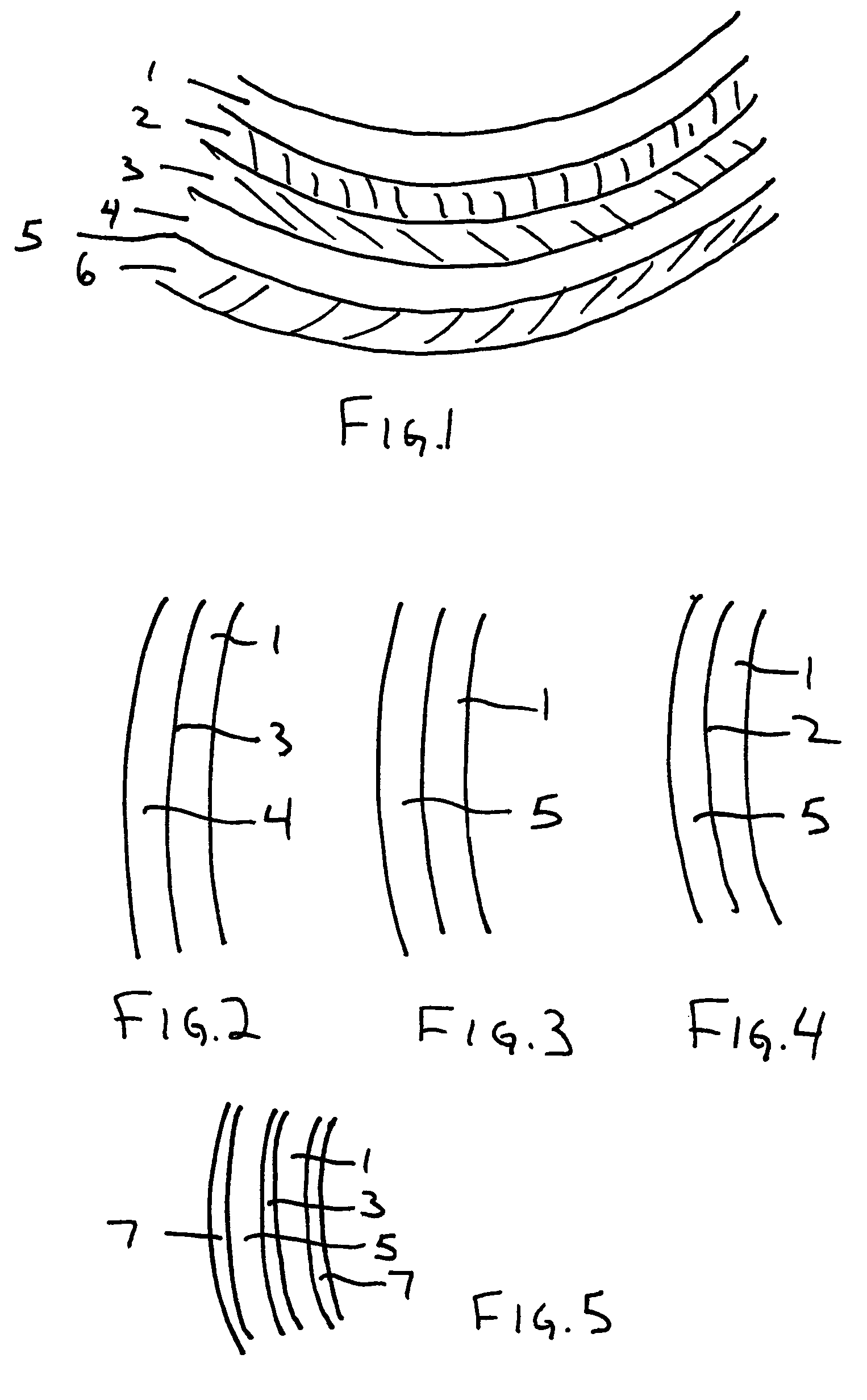

Image

  • Method of forming polarized or photochromic lenses by fusing polycarbonate with other plastic materials
  • Method of forming polarized or photochromic lenses by fusing polycarbonate with other plastic materials
  • Method of forming polarized or photochromic lenses by fusing polycarbonate with other plastic materials

Examples


example 1

[0062](S1) Adhesive glue: Adhesive glue was loaded into an injection tank and the bubbles remove.

[0063](S2) Primer coat solution: 60 parts by weight of a coating material, such as a high boiling acrylate; e.g., aliphatic urethane acrylate oligomer were taken with 1 part modified acrylamide and mixed together by stirring at 21° C. for 5 min. in a sealed environment not exposed to air or oxygen.

[0064](S3) Monomer: Thermosetting monomer (such as CR39, 1.56 etc., available from PPG US or Nihon Yushi Japan) was mixed with an IPP initiator and stored until ready for use at under −20° C.

[0065](S4) The corona discharge was applied.

[0066](S5) Polarized film: The film (available from Talex, TNK, Polateco etc., Japan) was held, preferably using a “no finger touch” device holder with which both sides of the lens or film are exposed to the corona discharge in a clean and safe manner, and the outside surfaces exposed steadily to a corona discharge unit (MultiDyne™ corona treating system, availabl...

example 2

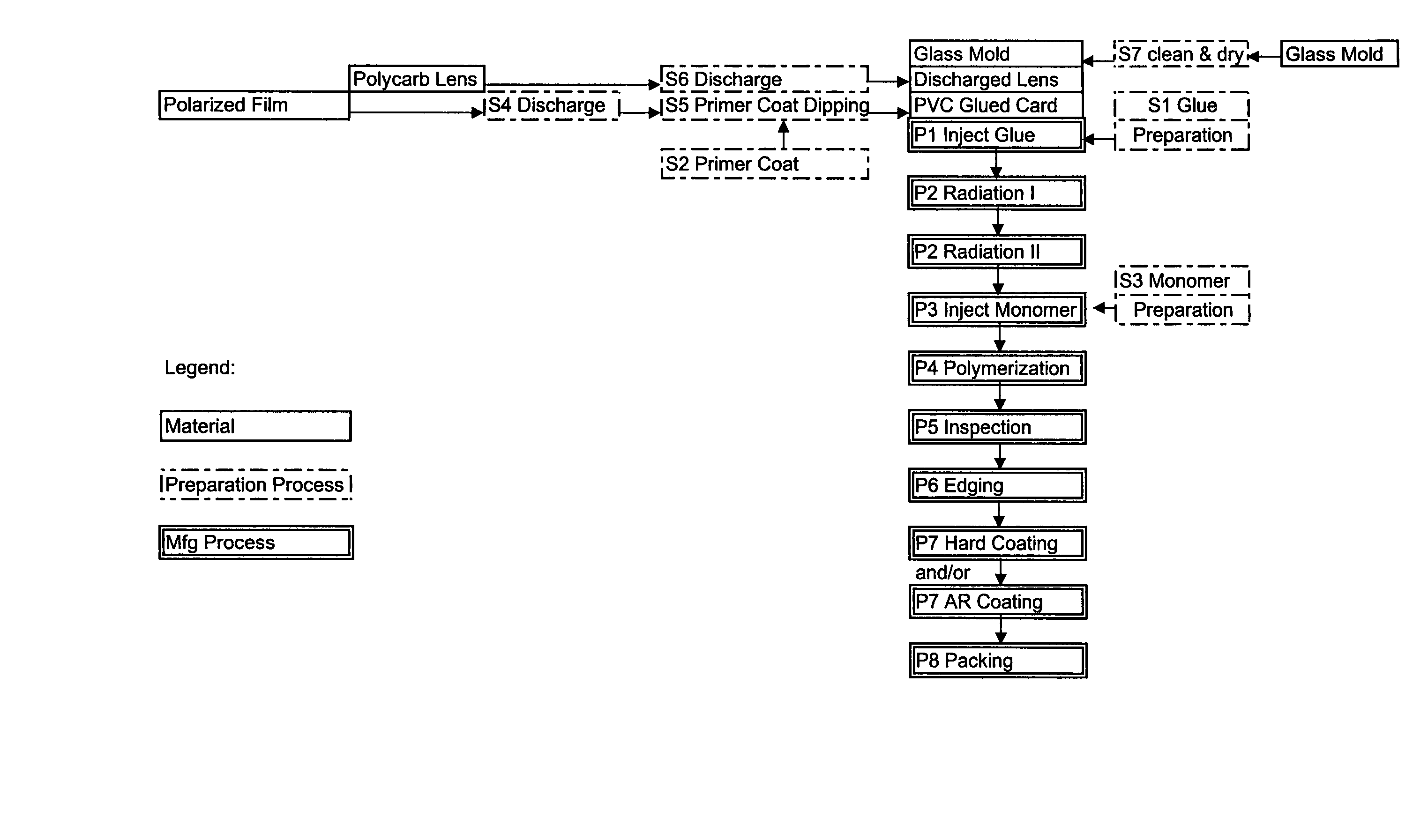
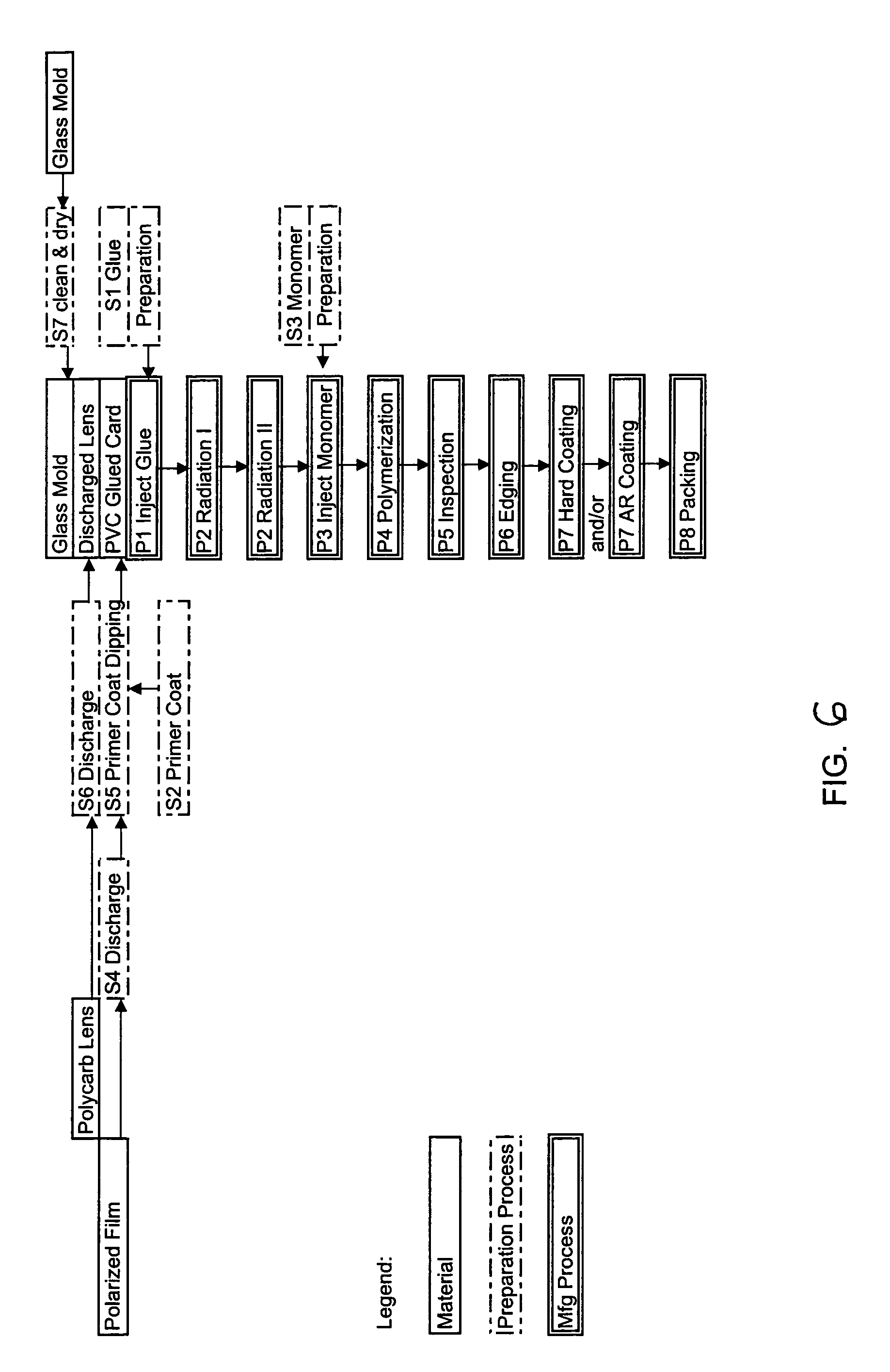
[0071](P1) Glue injection: The glass mold II (S8) was placed at a holder stand with the front side downward. The PVC glued card (S6) was overlapped at 180 degrees on the glass mold and 0.8 gram of glue was injected at generally the center of the PVC glued card. The polycarbonate lens (S7) was overlapped onto the PVC glued card and the lens pressed until glue was evenly distributed and applied.

[0072](P2) Radiation: The glued lens (P1) was cured on the convex side for 3 minutes and concave side for 3.5 minutes.

[0073](P3) Monomer injection: The new glass mold II (S8) was placed in a holder stand, front side downward. 2.7 gram of (S3) monomer was injected onto the glass mold (S8). the radiation cured lens (P2) was overlapped on top and maintained horizontally and kept horizontally in an oven tray.

[0074](P4) Polymerization: The lens (P3) was polymerized in an oxygen-free oven for 18 hours as per a controllable program.

[0075](P5) Separation and Drying: The polymerized lens (P4) was taken ...

example 3

[0081]Examples for glue curing at radiation.

[0082]Note: Curing factors (distance, power and time) are changeable provided the total curing energy second-mwatt / cm2 is enough. UV light: A commercially available UV light with major wavelength between about 340–400 nm was used. Metal halide: A commercially available metal halide lamp with major wavelength between about 365–420 nm was used. The light boxes were installed with hot air exhaust to prevent the polarizer from being damaged (should be less than about 100 degrees Celsius).

[0083]Table 1 below shows the experiment number, procedure and final cure details.

[0084]

TABLE 1Exper.No.PrecureFinal cure1Step 1. One 150 W UV light (15 cm far) fromStep 1. 300 W UV light (15 cm far) from PCpolarizer side for 20 sec.lens side for 3 minutesStep 2. Two 20 W UV light (15 cm far) fromStep 2. 300 W UV light (15 cm far) fromPC lens side for 20 sec. or longerpolarizer side for 3.5 minutes(Or do step 2 before step 1)2Simultaneously, do both steps 1 an...


PUM

PropertyMeasurementUnit
thicknessesaaaaaaaaaa
thicknessaaaaaaaaaa

Abstract

The invention provides techniques for making polycarbonate or plastic lenses. In one exemplary embodiment, for example, an electrical discharge is applied to a polarized film surface and a treatment applied on the polarized film to make a glue card. An adequate amount of adhesive glue is spread between the polarized film glue card and a polycarbonate lens, and a one-unit lens is formed by photochemical reaction technology. Thermosetting monomer is poured between the unit lens and a glass mold, and heated evenly to create a solid one-piece lens. The thermosetting monomer may be a photochromic or transparent monomer. These or substantially similar techniques may be used to produce polycarbonate polarized lenses, polycarbonate photochromic lenses, polycarbonate photochromic polarized lenses, plastic polarized lenses, plastic photochromic lenses, and plastic photochromic polarized lenses.

Description

CROSS-REFERENCE TO RELATED APPLICATION[0001]This application claims priority from provisional application No. 60 / 466,719, filed Apr. 30, 2003, entitled METHOD OF FORMING POLARIZED OR PHOTOCHROMIC LENSES BY FUSING POLYCARBONATE WITH OTHER PLASTIC MATERIALS.FIELD OF THE INVENTION[0002]The present invention relates generally to methods of bonding thermosetting and thermoplastic materials together to produce a single solid polarized and / or photochromic optical lens in polycarbonate. More particularly, the present invention provides methods for surface treating the plastic materials to promote effective bonding and provide improved optic properties.BACKGROUND OF THE INVENTION[0003]Sunlight is a mixture of vertical and horizontal wavelengths of light. A polarized lens selects either wavelength of light, vertical or horizontal, to pass through, and blocks the other wavelength. Thus, the reflection or glare from water surfaces, concrete roads, metal object, etc., will be significantly reduc...

Claims


Application Information

Patent Timeline
Patent Type & Authority Patents(United States)
IPC IPC(8): G02C7/02B29D11/00G02B1/04G02C7/06
CPCB29D11/0073G02B1/041
Inventor CHOU, SLOAN
Owner POLYLITE TAIWAN
Learn More