Optical sensor using a long period grating suitable for dynamic interrogation

a technology of optical sensors and gratings, applied in the field of optical sensors, can solve the problems of difficult to determine which reflections pertain to which meter or sensor, difficulty in continuously monitoring bragg wavelength shifts, and inability to use high frequency rate pulse sampling in a practical application, etc., to achieve accurate representation of dynamic events.

Inactive Publication Date: 2006-10-31
WEATHERFORD TECH HLDG LLC
View PDF8 Cites 10 Cited by
  • Summary
  • Abstract
  • Description
  • Claims
  • Application Information

AI Technical Summary

Benefits of technology

[0009]Disclosed herein is an optical sensor design and method for continually interrogating that sensor to produce an accurate representation of a dynamic event (such as a change in strain, pressure or temperature) being monitored by the sensor. The sensor design preferably constitutes continuous wave optical source/detection equipment coupled in series to a first fiber Bragg grating (FBG), a long period grating (LPG), and a second FBG formed in an optical waveguide. The LPG broadly attenuates light in the vicinity of the Bragg reflection wavelength λ2B of the second FBG, and this attenuation profile shifts i

Problems solved by technology

However, such high frequency rate pulsed sampling may not be possible in a practical application.
High rate sampling of FBG 10 could interfere with interrogation of the other optical sensors or meters multiplexed with FBG 10, and/or confused the reflected signals, mak

Method used


Image

  • Optical sensor using a long period grating suitable for dynamic interrogation
  • Optical sensor using a long period grating suitable for dynamic interrogation
  • Optical sensor using a long period grating suitable for dynamic interrogation

Examples


Embodiment Construction

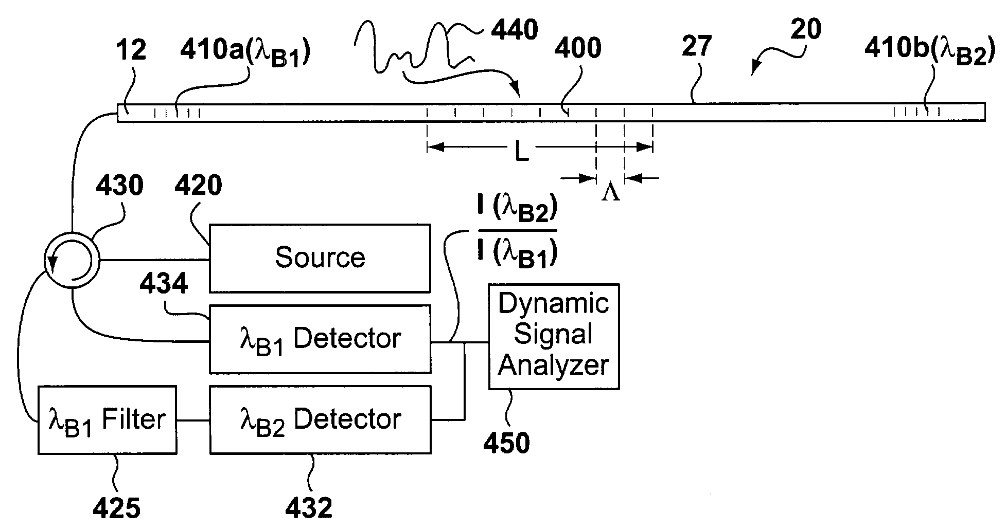
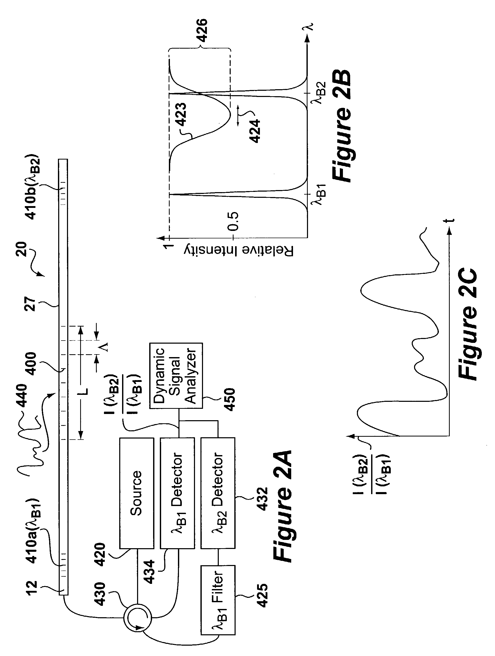
[0014]In FIG. 2A, the parameter-measuring FBG 10 of FIG. 1 has been replaced by a long period grating (LPG) 400 along the optical waveguide 12. The dynamic event 440 being sensed effects the LPG 400, which acts as the sensitive element as will be explained below. While capable of detecting different types of dynamic events 440, such as temperature variations, this disclosure assumes for simplicity that the dynamic event 440 constitutes a dynamic pressure, such as a seismic pressure wave, which is the application for which the improved sensor and interrogation technique was primarily designed. The spacing Λ of the index of refraction modulation in an LPG 400 is greater than normally used in a narrow band Bragg reflector, ranging on an order of over 25 microns, e.g., about 100 microns, and stretching over a length L of approximately 2 cm. The LPG 400 provides coupling of light propagating in the waveguide to forward propagating cladding modes which are eventually lost due to absorptio...


PUM


Abstract

Disclosed herein is an optical sensor design and method for continually interrogating that sensor to produce an accurate representation of a dynamic event (such as a change in strain, pressure or temperature) being monitored by the sensor. The sensor design preferably constitutes continuous wave optical source/detection equipment coupled in series to a first fiber Bragg grating (FBG), a long period grating (LPG), and a second FBG formed in an optical waveguide. The LPG broadly attenuates light in the vicinity of the Bragg reflection wavelength λ2B of the second FBG, and this attenuation profile shifts in wavelength in accordance with the dynamic event being monitored. Perturbation of the attenuation profile thus attenuates the intensity of the light reflected from the second FBG, i.e., I(λB2), because such reflected light must pass (twice) through the LPG. Accordingly, continually monitoring I(λB2) as a function of time allows the dynamic event to be recreated and processed accordingly. If necessary, I(λB2) can be normalized by dividing it by the intensity of the Bragg reflection wavelength from the first FBG, I(λB1), to discard attenuation within the system not related to the dynamic event being monitored.

Description

CROSS REFERENCES TO RELATED APPLICATIONS[0001]U.S. patent application Ser. No. 10 / 452,124 filed Jun. 2, 2003, now U.S. Pat. No. 6,955,085, entitled “Optical Accelerometer or Displacement Device Using A Flexure System,” filed concurrently herewith, contains subject matter related to that disclosed herein, and is incorporated herein by reference in its entirety.TECHNICAL FIELD[0002]This invention relates to an optical sensor, and more specifically to an optical sensor for monitoring dynamic events and associated interrogation methods.BACKGROUND ART[0003]Optical sensors are well known in the art, and have utility in a number of different measurement applications. For example, and as shown in FIG. 1, a fiber Bragg grating 10 (FBG 10) formed in an optical fiber 12 or other optical waveguide can be used to measure pressure or temperature. A FBG, as is known, is a periodic or aperiodic variation in the effective refractive index of a core of an optical waveguide, similar to that described ...

Claims


Application Information

Patent Timeline
IPC IPC(8): G02B6/00G01B11/16G01D5/353G01L1/24
CPCG01B11/165G01D5/35303G01L1/246G01B11/18
Inventor MACDOUGALL, TREVOR
Owner WEATHERFORD TECH HLDG LLC
Why Eureka
Try Eureka