
Method and arrangement for controlling an internal combustion engine

Inactive Publication Date: 2006-11-07
ROBERT BOSCH GMBH
View PDF17 Cites 6 Cited by
  • Summary
  • Abstract
  • Description
  • Claims
  • Application Information

AI Technical Summary

Benefits of technology

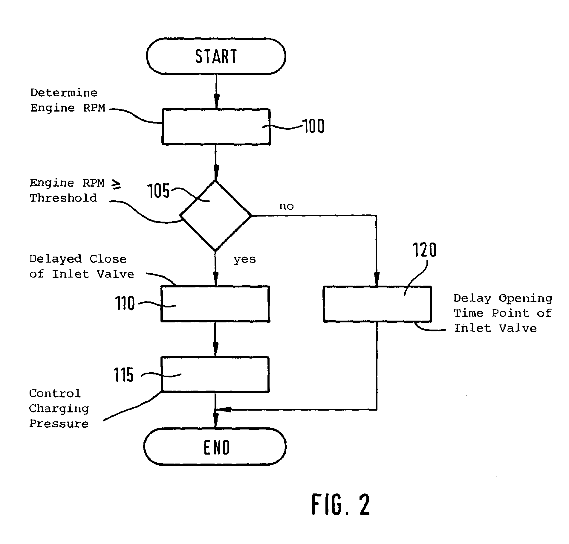
[0004]Compared to the above, the method of the invention and the arrangement of the invention for controlling an internal combustion engine afford the advantage that two operating states of the engine are distinguished in dependence upon an operating variable, especially the engine speed. In a first operating state during an intake operation, an opening of the inlet valve is delayed and, in a second operating state, a closure of the inlet valve is delayed and is carried out during a compression operation. In this way, the engine can be optimally operated in different operating states with different requirements as to the opening time of the inlet valve. Accordingly, in a first operating state, an increased charge of the cylinder is realized without use of an auxiliary compressor. In the second operating state, a reduction of the effective compression and therefore an increased resistance to knocking and a lower exhaust-gas temperature can be realized especially at full load operation and therefore a higher degree of efficiency is realized.
[0006]It is especially advantageous that a fresh air / fuel mixture, which is supplied to the engine, is compressed by means of an exhaust-gas turbocharger. With the exhaust-gas turbocharger, the effect of the post-charging of the cylinder because of a late opening of the inlet valve is amplified especially in the first operating state. In the second operating state, return losses because of the late closing of the inlet valve are compensated.
[0007]It is also advantageous that the pregiven threshold for the operating variable is so selected that the first operating state is a start-drive state. In this way, when using the engine speed as an operating variable, a possibly provided exhaust-gas turbocharger is supported by the above-described post-charging effect so that no unwanted start-drive weakness occurs. With this exhaust-gas turbocharger, there is, in the lowest rpm range, not the possibility of an adequate charging.

Problems solved by technology

With this exhaust-gas turbocharger, there is, in the lowest rpm range, not the possibility of an adequate charging.

Method used


Image

  • Method and arrangement for controlling an internal combustion engine
  • Method and arrangement for controlling an internal combustion engine
  • Method and arrangement for controlling an internal combustion engine

Examples


Embodiment Construction

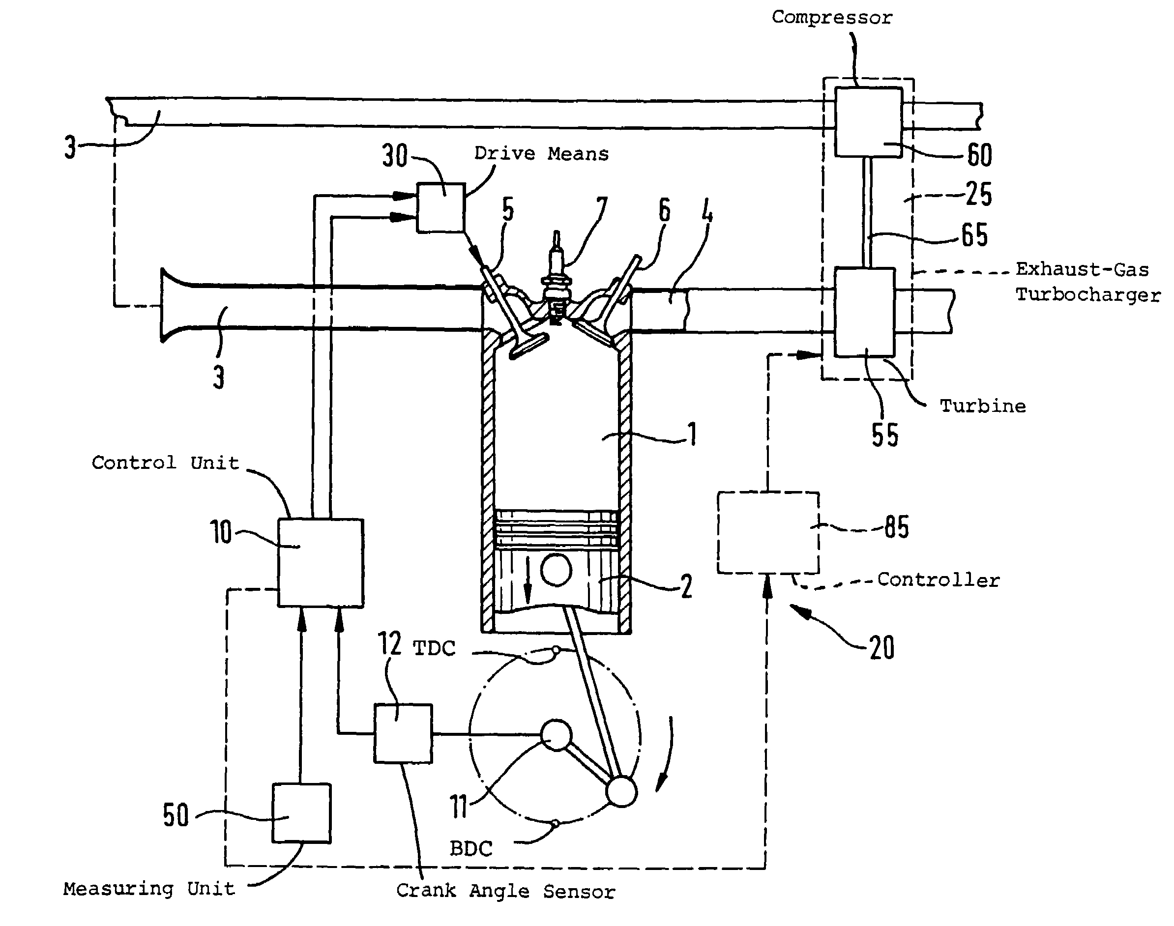
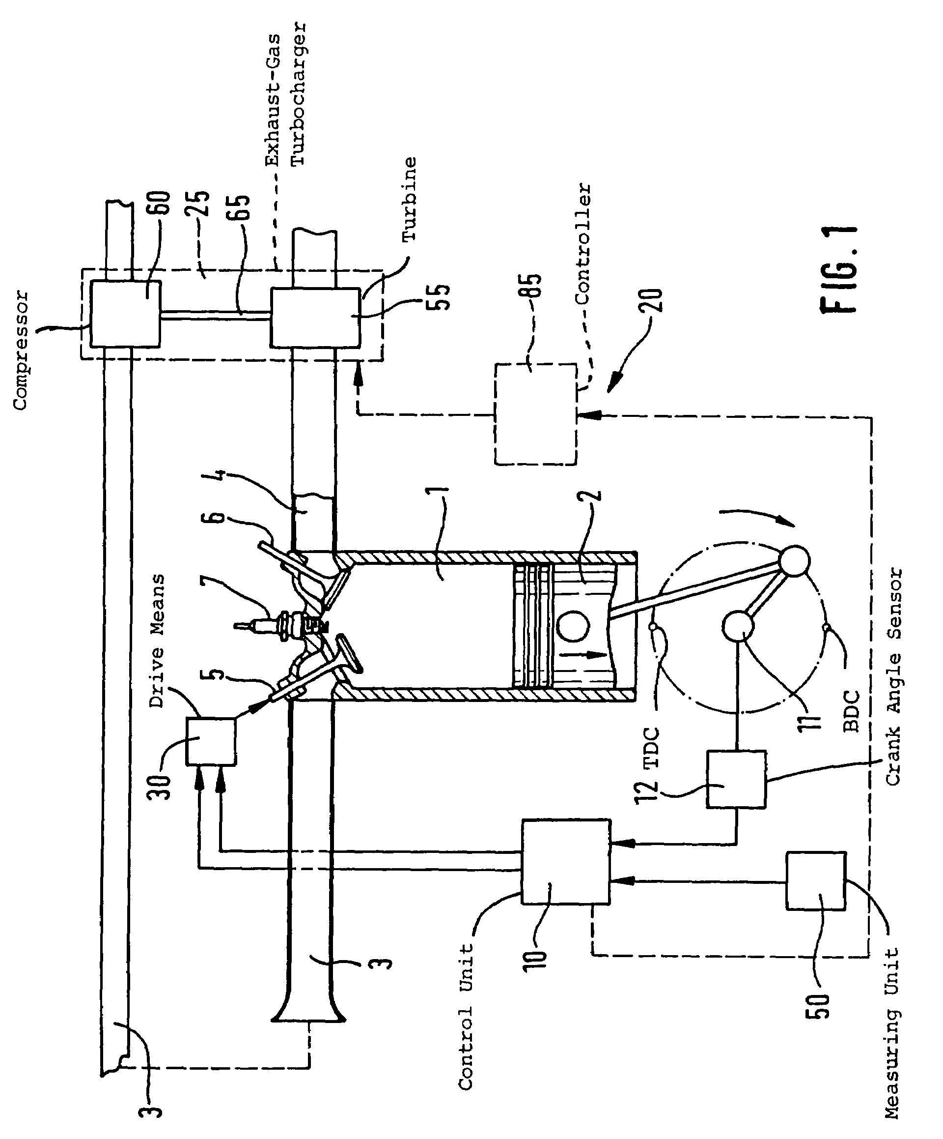
[0012]In FIG. 1, a cylinder 1 of an internal combustion engine 20 is shown with a piston 2 movable therein. The cylinder 1 has an inlet to an intake manifold 3 and an outlet to an exhaust-gas pipe 4. At least one inlet valve 5 is disposed in the inlet to the intake manifold 3 and at least one outlet valve 6 is arranged in the outlet to the exhaust-gas pipe 4 in the cylinder 1. Furthermore, a spark plug 7 is seated in the head of cylinder 1 and ignites the compressed air / fuel mixture in the cylinder 1. The position of a crankshaft 11, which is actuated by the piston 2, is detected by a crank angle sensor 12 and is supplied to a control 10 for controlling the internal combustion engine 20. The control 10 is identified in the following as a control unit. The control unit 10 can furthermore receive information via the crank angle sensor 12 as to the instantaneous position of the piston 2, that is, whether the piston 2 is disposed, for example, at top dead center (TDC) or at bottom dead ...


PUM


Abstract

The invention is directed to a method and an arrangement for controlling an internal combustion engine (20) which achieve an optimal efficiency in different operating states. An opening time of an inlet valve (5) of a cylinder (1) of the engine (20) is variably adjusted. Depending upon an operating variable, especially the engine speed, two operating states of the engine (20) are distinguished. In a first operating state, during an intake operation, an opening of the inlet valve (5) is delayed. In a second operating state, a closing of the inlet valve is delayed and carried out during a compression operation.

Description

BACKGROUND OF THE INVENTION[0001]Internal combustion engines having fully variable valve controls are known, for example, in the form of an electro-hydraulic valve control.[0002]Furthermore, German patent publication 198 46 111 discloses a method for increasing the torque of an internal combustion engine. The throttle flap in the intake manifold is closed at the beginning of an intake operation of the particular cylinder so that a post-charging effect, which increases the torque, occurs also at low engine speed. The throttle flap is again opened after a delay time. The delay time is so dimensioned that a pressure wave, which arises in the intake manifold because of the closing of the throttle flap, reaches one or several inlet valves present on the cylinder directly in advance of their closing and effects a post-charging of the cylinder.[0003]Furthermore, the vehicle Eunos 800N is known, for example, from the Mazda Company which has an engine configured as a Miller engine. Here, the...

Claims


Application Information

Patent Timeline
IPC IPC(8): F01L1/34F02D13/02F02D41/00F02D41/06
CPCF01L1/34F02D13/0234F02D13/0269F02D41/0002F02D41/062F01L2800/00F02B2275/32F02D13/0253F02D41/0007F02D2041/001Y02T10/142Y02T10/42Y02T10/12Y02T10/40
Inventor BAEUERLE, MICHAEL
Owner ROBERT BOSCH GMBH
Learn More