Nacelle inlet lip anti-icing with engine oil

a technology of engine oil and inlet lip, which is applied in the direction of engine cooling apparatus, air transportation, jet propulsion plants, etc., can solve the problems of reducing the overall engine performance, power output, efficiency and/or cooling capacity of the power plant, and limiting the quantity of air being fed to the engine, so as to prevent ice buildup

Inactive Publication Date: 2006-11-07
PRATT & WHITNEY CANADA CORP
View PDF17 Cites 78 Cited by
  • Summary
  • Abstract
  • Description
  • Claims
  • Application Information

AI Technical Summary

Benefits of technology

[0005]It is another object of the present invention to provide a system which will prevent ice formation on the aircraft engine nacelle inlet lip and will provide an oil cooler for the engine lubricating oil system.
[0008]There is further provided, in accordance with the present invention, a method of preventing ice build up on a nacelle inlet lip and cooling engine oil, comprising the steps of: providing a nacelle housing a gas turbine engine and having a conduit within an inlet lip thereof defining a circumferential oil passage therein, enabling heat transfer communication between said conduit and an outer surface of said inlet lip; and circulating pressurized engine oil used to lubricate said gas turbine engine through conduit; thereby cooling said engine oil and heating said outer surface of said inlet lip.

Problems solved by technology

The build-up of ice on a nacelle surrounding the power plant limits the quantity of air being fed to the engine.
This reduction in inlet airflow can result in a reduction of power output, efficiency and / or cooling capacity of the power plant.
However, hot air bled from the engine core reduces overall engine performance and electrical heating systems draw electrical power which furthers non-propulsive load imposed on the engine.

Method used


Image

  • Nacelle inlet lip anti-icing with engine oil
  • Nacelle inlet lip anti-icing with engine oil
  • Nacelle inlet lip anti-icing with engine oil

Examples


second embodiment

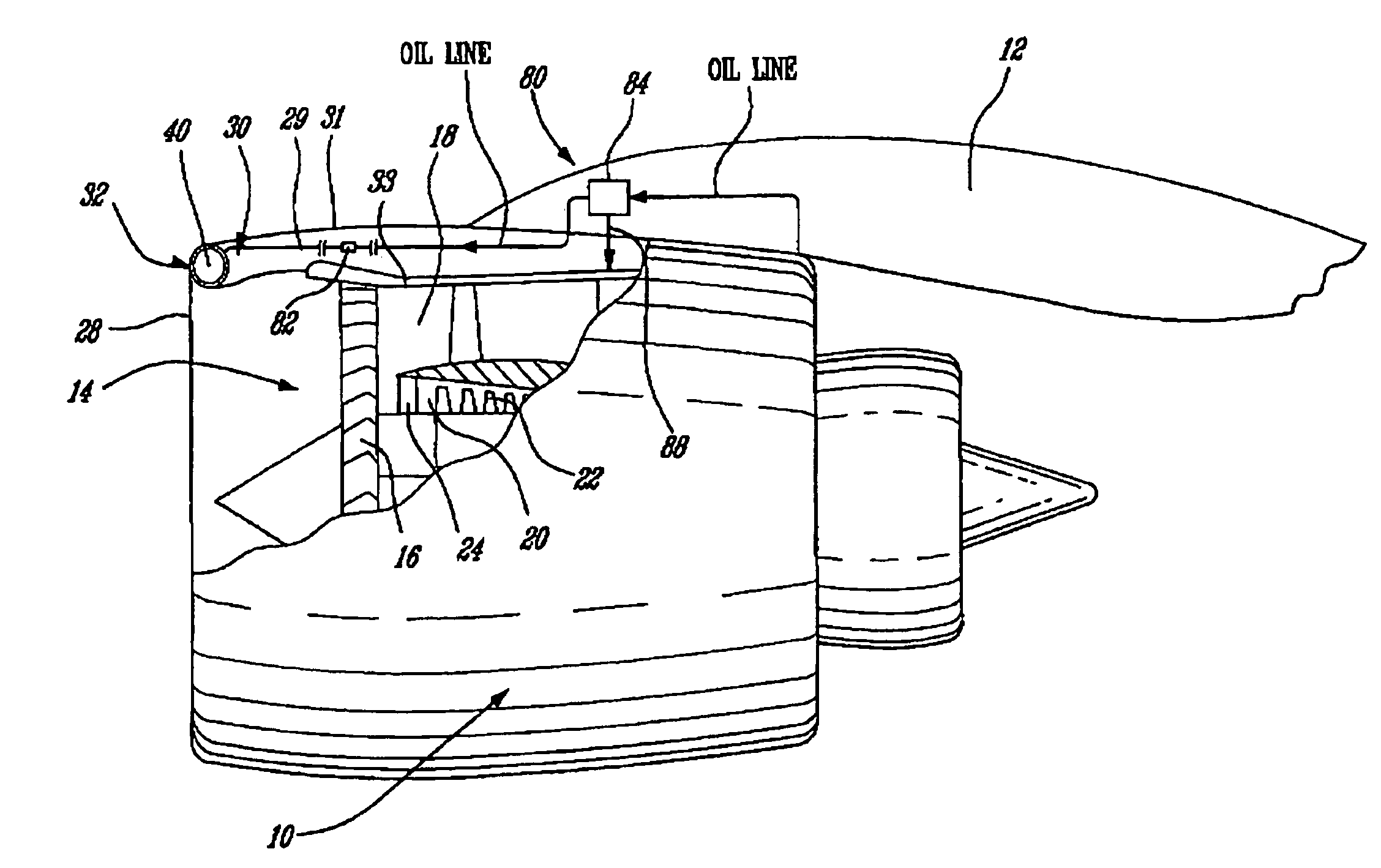
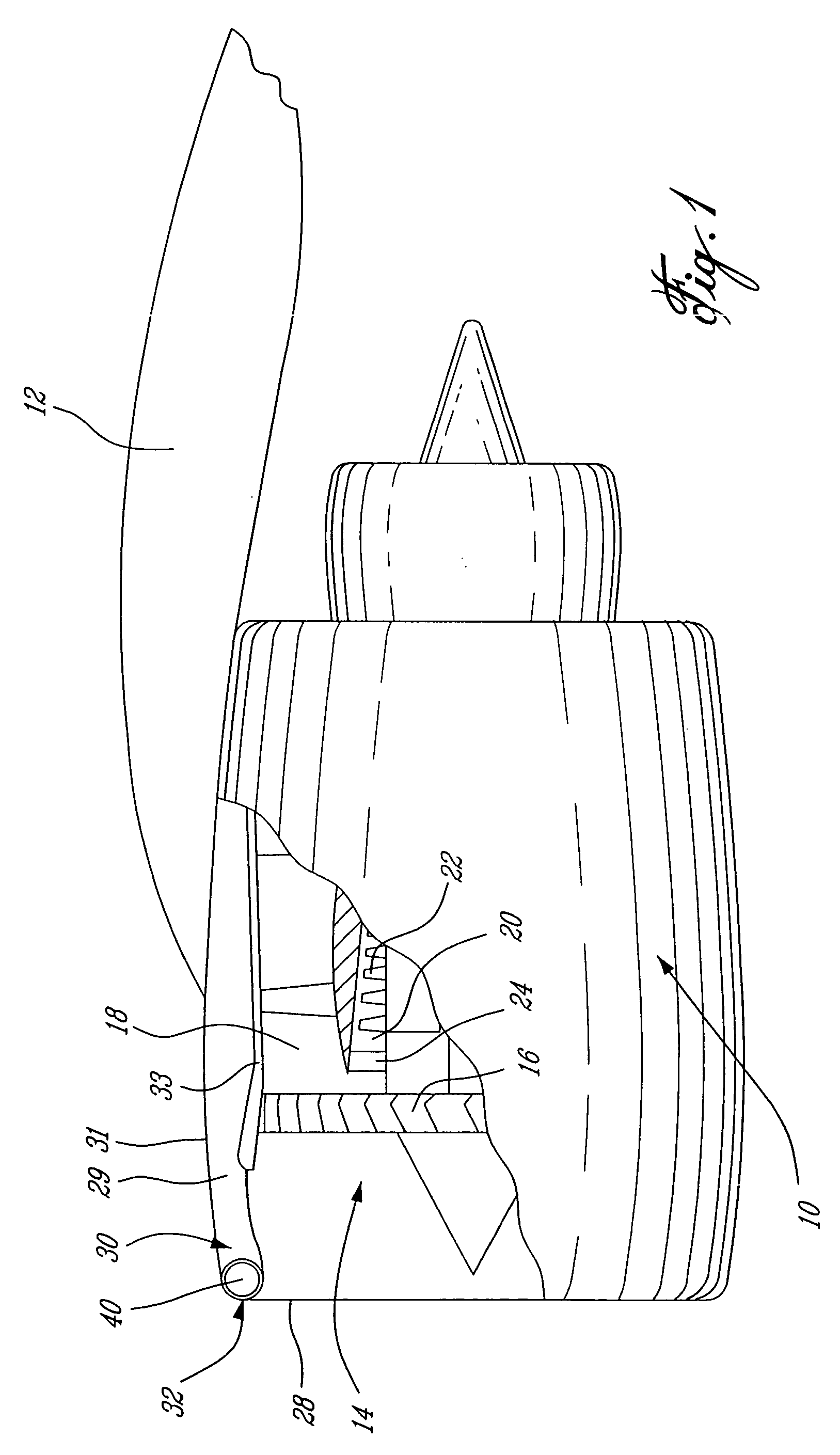
[0023]Referring now to the present invention depicted in FIG. 3a, the nacelle 110 is cast with the conduit 130, which defines the annular oil passage 140, integrally defined within the upstream end thereof. Annular retaining walls 144 within the hollow cavity 129 of the nacelle 110 define the oil passage 140 upstream thereof, between the retaining walls 144 and the curved leading edge of the inlet lip 128. At least an integral oil inlet conduit 146 and an oil outlet conduit (not shown) are similarly cast within the nacelle 110 near the inlet lip 128, such that oil can be pumped into the oil passage 140 and can be withdrawn therefrom once it has sufficiently cooled due to heat transfer to the outer surfaces of the nacelle inlet lip 128. Other structural elements such as support struts 148, which are provided to ensure adequate stiffness, are similarly integrally cast within the nacelle 110.

first embodiment

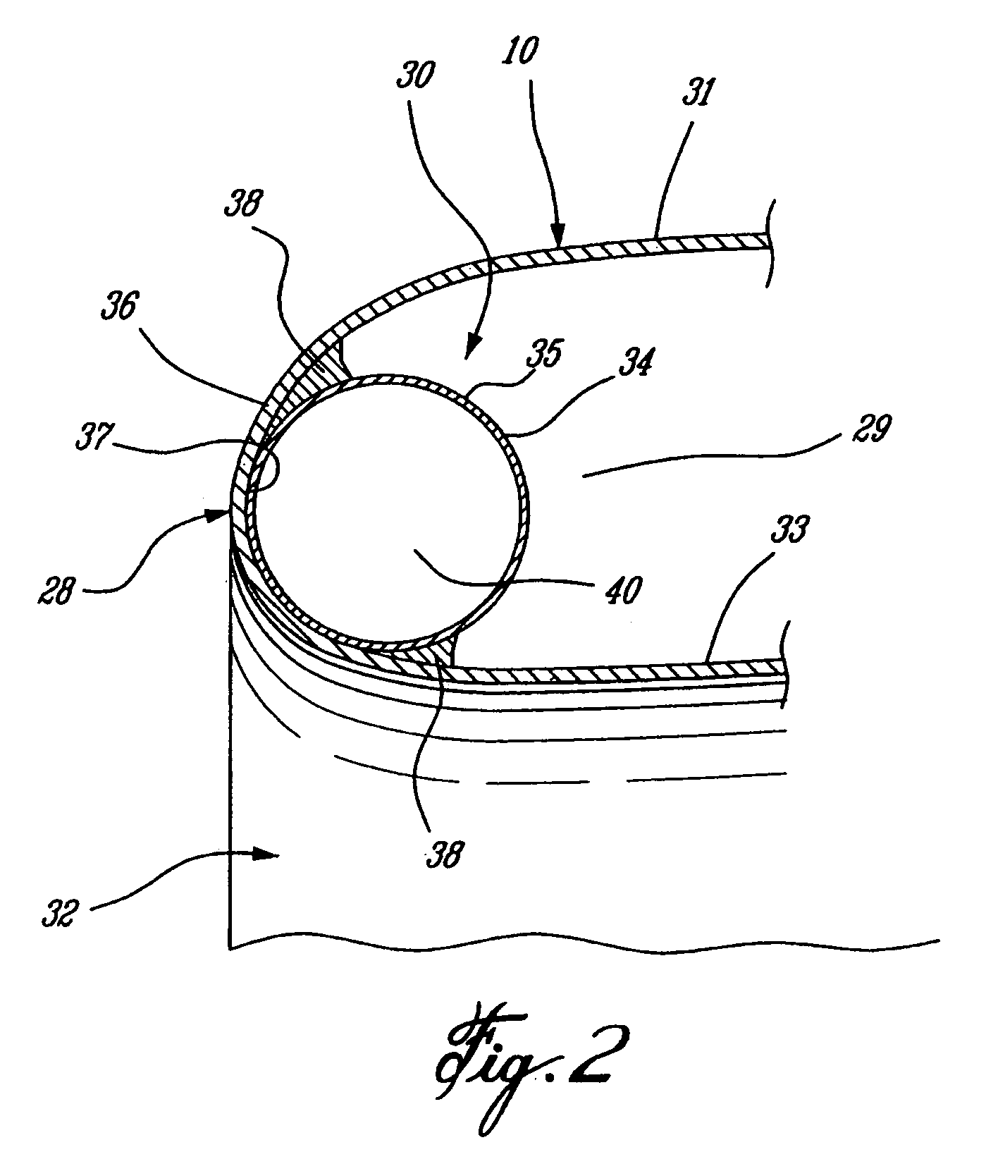
[0024]In contrast to the tube 34 which defines the oil passage 40 in FIG. 2, the advantage of casting the conduit 130 defining the oil passage 140 within the inlet lip 128 as depicted in FIG. 3a is that the shape and features of the oil passage 140 can be specifically selected and optimized to suit the particular anti-icing requirements for the intended application of the nacelle 110. Further, by casting the entire inlet lip 128 of the nacelle 110, the structure and the integrally defined passages therein can be manufactured to an exact required configuration with very little minimal post-production work, such as finish machining, polishing and welding for example, being necessary. This considerably saves on manufacturing time and expense required for the production of the finished part.

third embodiment

[0025]FIG. 3B is similar to that of FIG. 3A, however the conduit 130 further comprises an internal tube 152, which is integrally cast within the inlet lip 128 and defines the oil passage 140 therewithin. The internal tube 152 extends through the full circumference of the nacelle inlet and is comprised of a metal having a higher melting point than that of the base material of the nacelle 110, such that it can be integrally cast therein. The additional internal tube 152 integrally cast within the nacelle inlet lip 128 provides added protection against potential foreign object damage to the inlet lip 128 in comparison with the tube-less embodiment depicted in FIG. 3A. Therefore, should a foreign object strike the inlet lip 128 of the nacelle 110, the added integrally cast tube 152 further protects the oil passage 140 against a possible breach which would result in oil pressure loss. Another advantage of using an integrally cast tube 152 is that such pre-manufactured tubes are more cons...


PUM


Abstract

A nacelle for housing a gas turbine engine having a pressurized oil system for lubricating components thereof comprises an inlet lip defining a leading edge of the nacelle, the inlet lip having a conduit therein in fluid flow communication with the pressurized oil system of the gas turbine engine and defining an oil passage for circulation of pressurized engine oil therethrough. The conduit is in heat transfer communication with an outer surface of the inlet lip.

Description

TECHNICAL FIELD[0001]The present invention relates generally to de-icing and anti-icing systems for use with aircraft engines, and more particularly to a combined engine oil cooler and anti-icing system for an aircraft engine nacelle.BACKGROUND OF THE INVENTION[0002]Operation of aircraft power plants in adverse weather conditions or at high altitudes can sometimes lead to ice forming on the exposed surfaces of the power plant inlet. The build-up of ice on a nacelle surrounding the power plant limits the quantity of air being fed to the engine. This reduction in inlet airflow can result in a reduction of power output, efficiency and / or cooling capacity of the power plant. Systems used to prevent or remove ice formation on aircraft nose cones or wing leading edges are well known. Engine inlet anti-icing systems are also used and commonly employ a thermal source, such as hot air bled from the engine core or an electrical heating element, which is applied to the nacelle inlet to melt or...

Claims


Application Information

Patent Timeline
Patent Type & Authority Patents(United States)
IPC IPC(8): B64D15/06B64D33/02F02C7/047F02C7/14
CPCB64D15/06B64D33/02F02C7/047F02C7/14B64D2033/0233B64D2033/0286Y02T50/675Y02T50/60
Inventor BAPTIST, PRABA KHARANBHARATH, KEPPEL NYRON
Owner PRATT & WHITNEY CANADA CORP
Why Eureka
Try Eureka