Inductive thermal plasma torch

Inactive Publication Date: 2006-11-07
ALCATEL LUCENT SAS
View PDF7 Cites 11 Cited by
  • Summary
  • Abstract
  • Description
  • Claims
  • Application Information

AI Technical Summary

Benefits of technology

[0014]The solution advocated by the invention concerns an improvement in the ignition device according to the fourth prior art. In order to avoid the problems of arcing, the igniter is carried by its support at one end thereof, that end being insulated from the electrical ground. In order nevertheless to allow initiation, a calibrated electrically conductive connection connects the igniter to the electrical ground. This electrically conductive connection is calibrated in such a manner as to be both sufficiently electrically insulating to avoid the creation of electric arcs that may damage the torch and sufficiently electrically conductive to initiate the discharge in the plasma. For that purpose, in t

Problems solved by technology

However, the plasma obtained with argon is very short, because argon is a monoatomic gas.
The conventional ignition devices will not be suitable for cold-cage torches.
Indeed conventional ignition devices will cause violent electrical arcs and destruction of certain parts or certain components of the cold-cage torch, or will be totally ineffective.
In a cold-cage torch, as in a conventional quartz torch, the electromagnetic field does not allow spontaneous ionisation of the plasma gas, which is why thermal or electrical initiation is necessary.
This ignition device has the drawback of being limited to conventional quartz torches, made of quartz and having a single thickness, that is to say, low-output torches.
Given that the use of graphite electrodes is complex and difficult, this first ignition device is complex and difficult and therefore cannot readily be used industrially.
This second ignition device is either able to effect initiation of the plasma provided that a very high power is applied which, when the ends are well-shaped in the form of a point, may destroy the torch by the violence of the ignition or, when the ends are blunted and have become rounded, it may no longer function correctly and no longer cause initiation at all, which rapidly and inevitably occurs after several ignition attempts.
This second device is consequently not very practical, especi

Method used


Image

  • Inductive thermal plasma torch
  • Inductive thermal plasma torch

Examples


Embodiment Construction

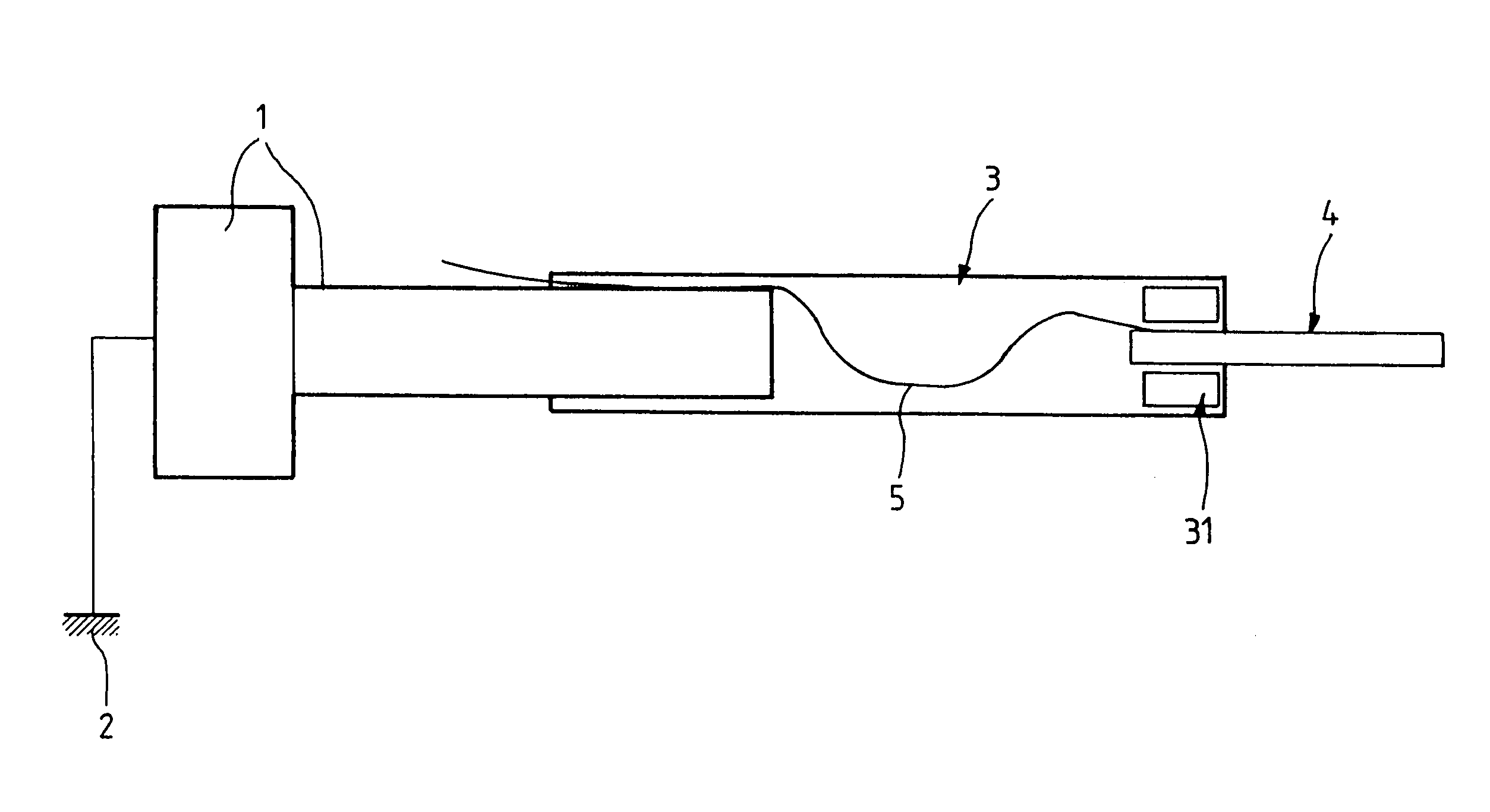
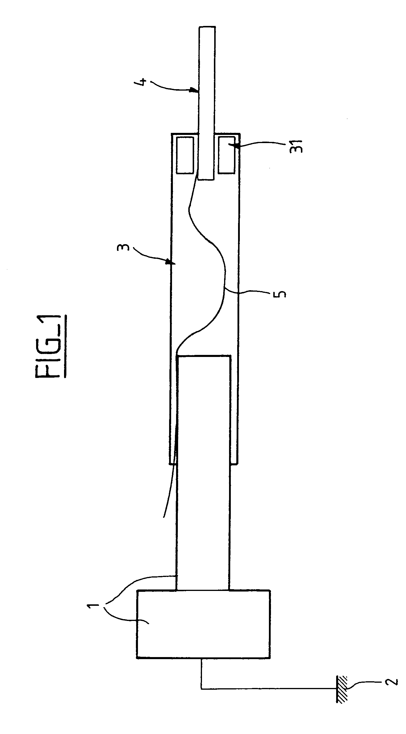
[0019]FIG. 1 is a diagramatic representation of a view in section of an ignition device for a cold-cage torch according to the invention. The ignition device comprises a support comprising on the one hand an electrically conductive end 1, which is connected to ground 2 of the plant, and on the other hand an electrically insulating end 3, which carries an igniter 4 for initiating the plasma in the torch. The igniter 4 is supported by the electrically insulating end 3. A calibrated electrically conductive connection 5 connects the igniter 4 to the electrically conductive end 1 of the support.

[0020]In one detailed embodiment, provided merely by way of example, the igniter 4 is held on the electrically insulating end 3 of the support by way of a high-temperature mesh tape 31. The electrically conductive end 1 is made of stainless steel (inox). The electrically insulating end 3 is a quartz tube. The igniter is made of graphite. The calibrated electrically conductive connection 5 is a cop...


PUM

PropertyMeasurementUnit
Diameteraaaaaaaaaa
Diameteraaaaaaaaaa
Electrical conductivityaaaaaaaaaa

Abstract

The invention relates to an inductive thermal plasma torch comprising a confinement tube that comprises, longitudinally in relation to the tube, metal fingers which are insulated from each other, an ignition device that comprises an igniter (4) and an igniter support (1, 3), the purpose of the igniter (4) being to initiate a discharge in the plasma of the torch, the support having an electrically conductive end (1) which is connected to the electrical earth (2) of the plant and another, electrically insulating, end (3) which carries the igniter, the ignition device also comprising an electrically conductive connection (5) connecting the igniter (4) to the electrically conductive end (1) of the support so that the igniter is able to initiate the discharge in the plasma, the electrically conductive connection (5) having a section that is sufficiently narrow to limit the intensity of the current capable of passing through the igniter (4) in order to avoid electrical arcing by capacitive discharge between the ignition device and another part of the torch.

Description

BACKGROUND[0001]1. Field of the Invention[0002]The invention relates to the field of inductive thermal plasma torches and more precisely to the field of so-called “cold cage” torches.[0003]2. Description of Related Art[0004]An inductive thermal plasma torch uses a plasma gas, for example filtered or reconstituted air, which is injected at the base of the torch, it being possible for the reagents to be injected either at the base of the torch or at the tip of the torch. Compared with a conventional torch, having a water-cooled quartz chamber, the maximum output of which is approximately 150 kW, a cold-cage torch enables outputs of from 500 kW to 1 MW or thereabouts to be obtained. In addition, the life of a cold-cage torch is superior to that of a conventional quartz torch. The cold-cage torch has a confinement tube essentially composed of conductive confinement fingers that extend longitudinally in relation to the tube and are advantageously made of metal material, for example coppe...

Claims


Application Information

Patent Timeline
IPC IPC(8): B23K10/00C03B37/012H05H1/30H05H1/34H05H1/36
CPCC03B37/01291H05H1/30H05H1/36H05H2001/3426H05H2001/3473H05H1/3421H05H1/3473
Inventor COELHO, DANIELDUMONT-MONNET, JEAN-PASCALRIPOCHE, PIERRE
Owner ALCATEL LUCENT SAS
Why Eureka
Try Eureka