
Power amplifier control using a switching power supply

a power amplifier and switching power supply technology, applied in the direction of amplifiers, amplifiers with semiconductor devices only, amplifiers with semiconductor devices, etc., can solve the problem of power consumption of mobile phones, and achieve the effect of reducing the magnitude of the spur and reducing the voltage rippl

Active Publication Date: 2006-11-07
QORVO US INC
View PDF23 Cites 55 Cited by
  • Summary
  • Abstract
  • Description
  • Claims
  • Application Information

AI Technical Summary

Benefits of technology

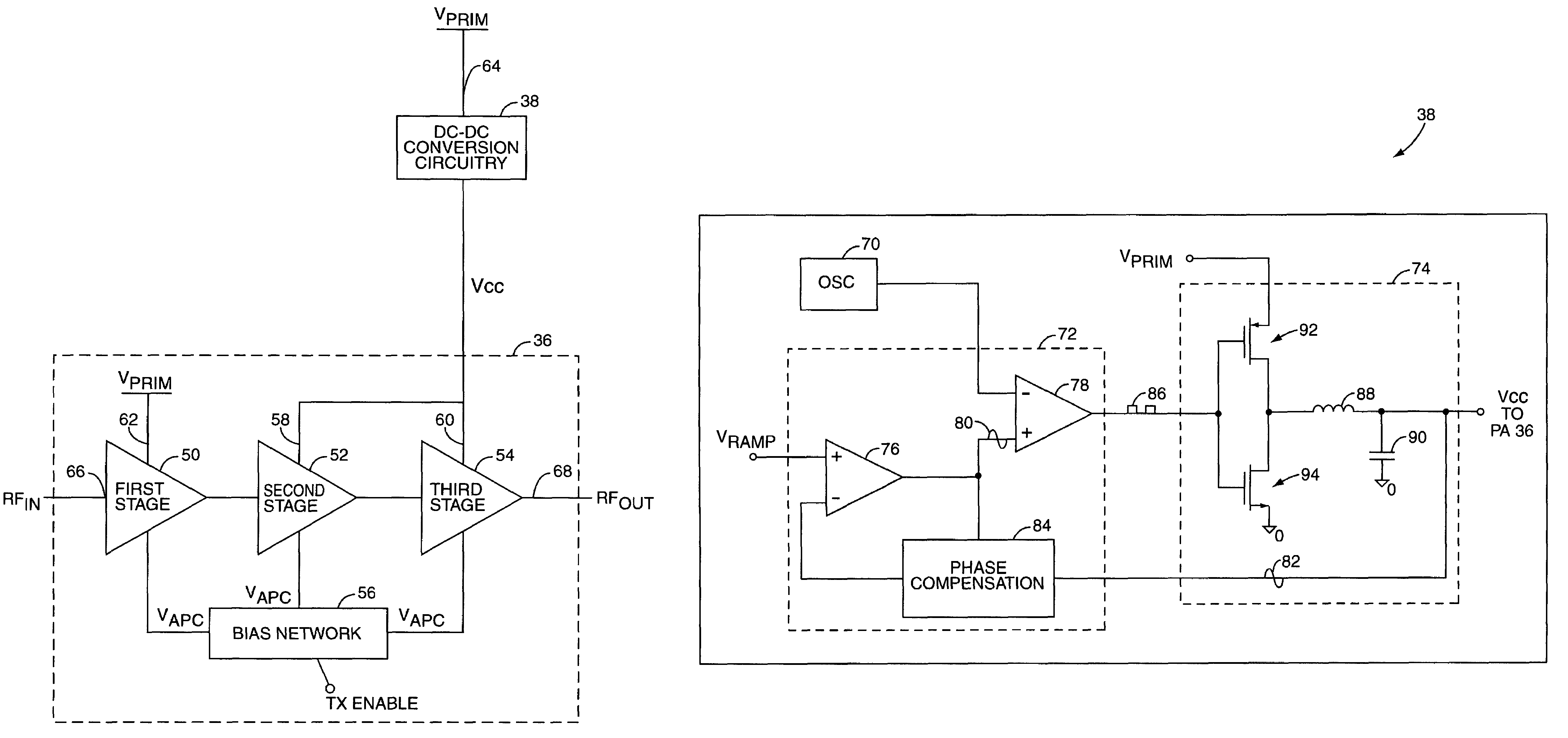
[0007]In one embodiment, the switching DC—DC conversion circuitry includes an oscillator, a converter control system, and a power train. The power train generates the variable supply voltage based on a control signal from the converter control system. The converter control system generates the control signal and controls a duty cycle of the control signal based on the adjustable power control signal and a clock signal. In order to reduce effects of the voltage ripple in the variable supply voltage caused by the clock signal, which defines the switching frequency of the switching DC—DC conversion circuitry, the oscillator may operate to periodically change the frequency of the clock signal, thereby periodically changing the frequency of the voltage ripple in the supply voltage. As a result, the spurious energy in the output of the power amplifier caused by mixing of a radio frequency (RF) input signal with the frequency of the voltage ripple is spread over multiple frequencies. In another embodiment, the oscillator may operate to change the frequency of the clock signal at a second frequency that is inversely related to the frequency of the clock signal, thereby further reducing the spurious energy in the output of the power amplifier.
[0009]In another embodiment, the switching DC—DC conversion circuitry is a multi-phase DC—DC converter. The multi-phase DC—DC converter includes a multi-phase converter control system, a multi-phase power train, and an oscillator. In general, the multi-phase DC—DC converter reduces a voltage ripple in the variable supply voltage as compared to a single-phase DC—DC converter, thereby reducing the magnitude of the resultant spurs in the output of the power amplifier.

Problems solved by technology

In large part, the power consumption of a mobile telephone is dependent upon the RF efficiency of a power amplifier in the transmit chain that operates to amplify a transmit signal prior sending the signal to the antenna for transmission.

Method used


Image

  • Power amplifier control using a switching power supply
  • Power amplifier control using a switching power supply
  • Power amplifier control using a switching power supply

Examples


Embodiment Construction

[0023]The embodiments set forth below represent the necessary information to enable those skilled in the art to practice the invention and illustrate the best mode of practicing the invention. Upon reading the following description in light of the accompanying drawing figures, those skilled in the art will understand the concepts of the invention and will recognize applications of these concepts not particularly addressed herein. It should be understood that these concepts and applications fall within the scope of the disclosure and the accompanying claims.

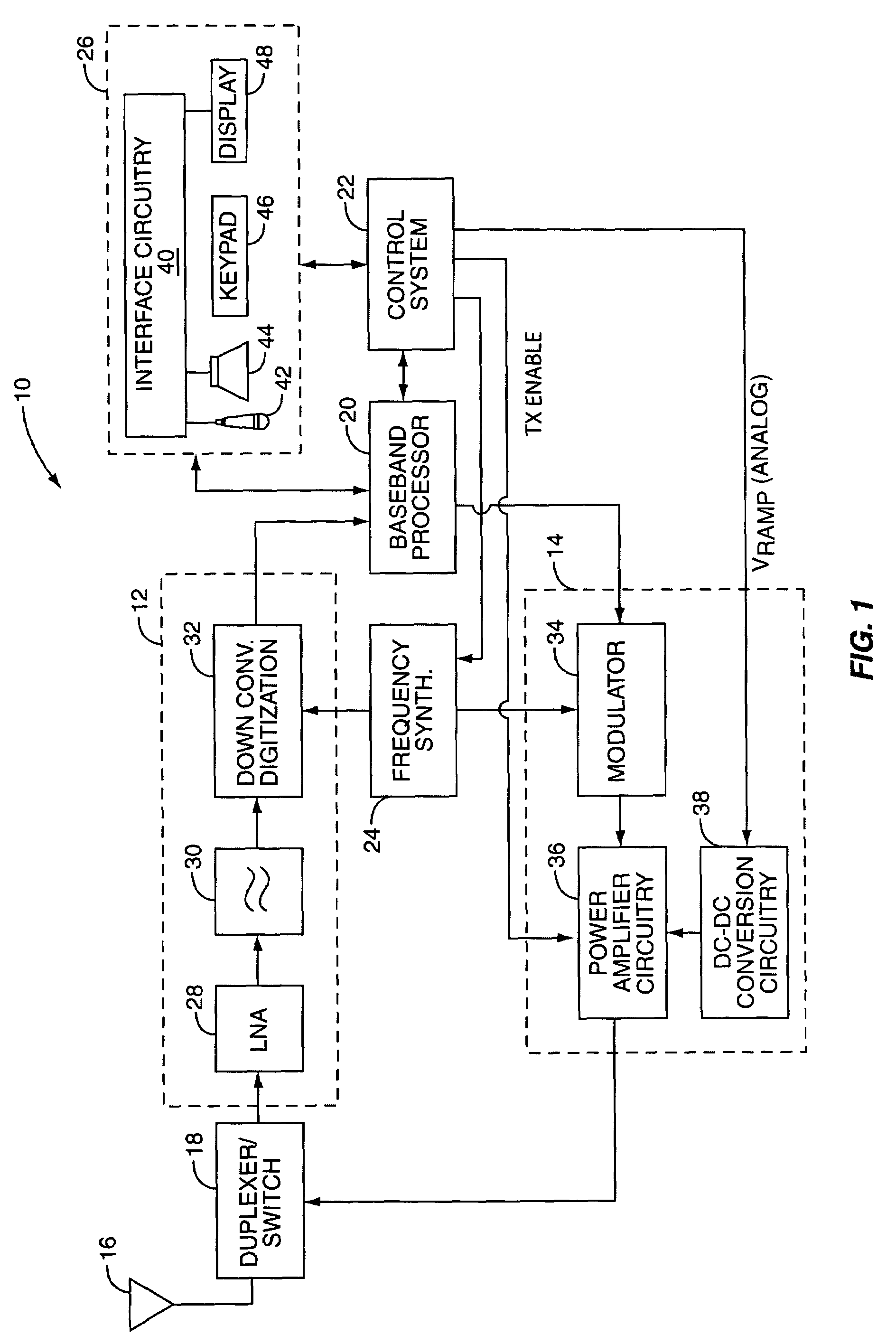
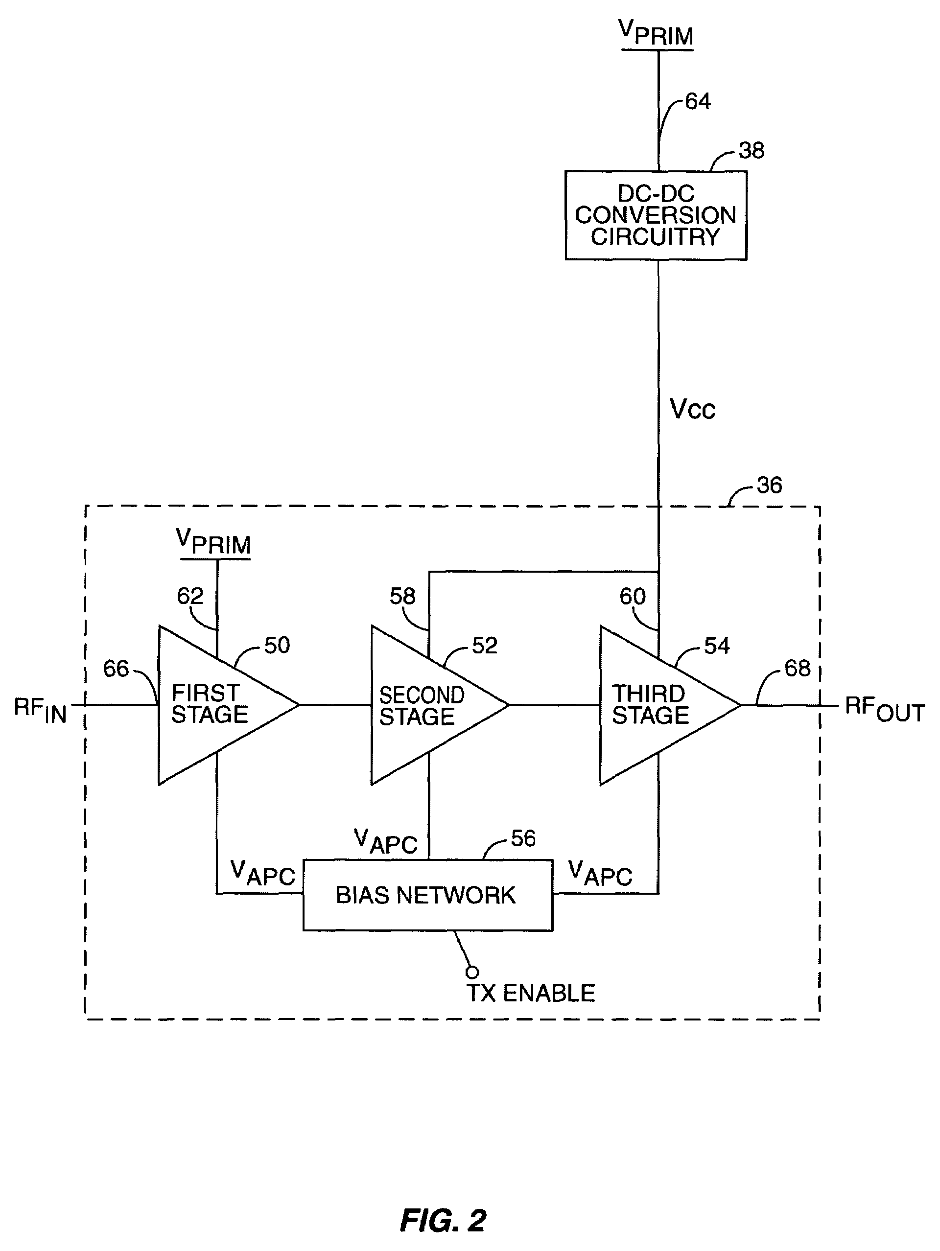
[0024]Accurate and discrete power control can be achieved by varying the DC voltage supplied to the collectors or drains of the final amplifier stages of a power amplifier. As opposed to the prior art, radio frequency (RF) output power for the present invention has very little dependence on frequency, temperature, or input power when the supply voltage for the final amplifier stages is regulated to control output power. Adjusting ...


PUM


Abstract

A system is provided for adjusting an output power of a multi-stage power amplifier by controlling a supply voltage provided to one or more output amplifier stages of the power amplifier using a switching DC—DC converter. In general, the system includes a power amplifier including an input amplifier stage and one or more output amplifier stages coupled in series with the input amplifier stage. The one or more output amplifier stages receive a variable supply voltage from switching DC—DC conversion circuitry. The switching DC—DC conversion circuitry provides the variable supply voltage based on an adjustable power control signal. By controlling the variable supply voltage provided to the one or more output stages, the switching DC—DC conversion circuitry controls an output power of the power amplifier based on the adjustable power control signal.

Description

FIELD OF THE INVENTION[0001]The present invention relates to controlling the output power of a multistage radio frequency power amplifier by adjusting the power supply voltage level applied to the final stages of the power amplifier using a switching DC—DC converter.BACKGROUND OF THE INVENTION[0002]In recent years, worldwide demand for wireless cellular communications has increased dramatically. Mobile telephones manufactured to meet this burgeoning demand must adhere to standards such as the Global System for Mobile Communications (GSM) standard. Another standard, the Digital Cellular System (DCS) standard, is based on GSM, but is directed towards higher cell density and lower power. A third standard, Personal Communications Services (PCS), is a “catch all” for many digital cellular systems, including GSM, operating in North America. These standards all require precise output power control over a large dynamic range in order to prevent a transmitter located in one cell from interfe...

Claims


Application Information

Patent Timeline
Patent Type & Authority Patents(United States)
IPC IPC(8): H03F3/04
CPCH03F1/0227H03F3/217
Inventor DENING, DAVIDMADSEN, ULRIK R.STEEL, VICTOR E.JORGENSON, JON D.KAY, MICHAEL R.
Owner QORVO US INC
Learn More