
Circulating body and fixing device

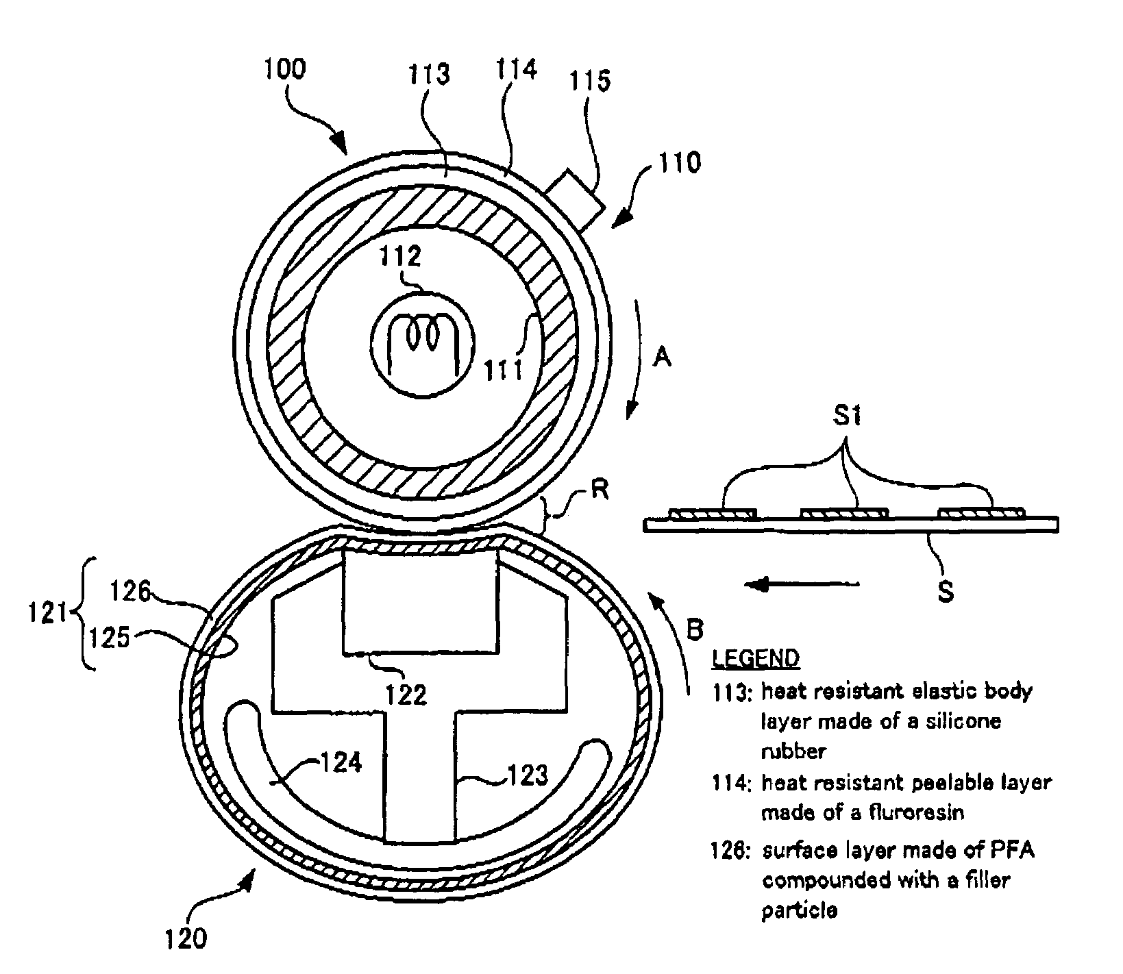
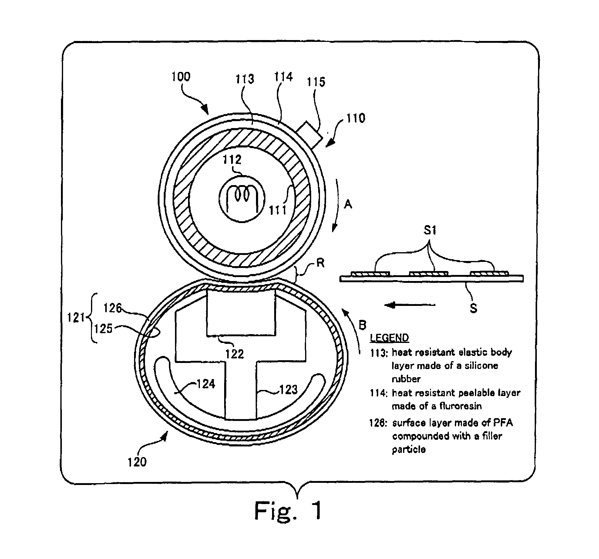
a technology of fixing device and circulating body, which is applied in the direction of ohmic-resistance heating, shafts and bearings, instruments, etc., can solve the problems of inferior fixing characteristics of other fixing methods, odor and sanitation, solvent fixing methods and pressure fixing methods, etc., and achieve high running stability of recording sheets, high reliability, and remarkable suppression of paper wrinkles and image defects

Inactive Publication Date: 2006-11-07
FUJIFILM BUSINESS INNOVATION CORP
View PDF7 Cites 2 Cited by
  • Summary
  • Abstract
  • Description
  • Claims
  • Application Information

AI Technical Summary

Benefits of technology

The present invention provides a solution to the problem of unstable running of a recording sheet, paper wrinkles and image defects in a recording device. This is achieved by providing a circulating body with a surface layer having a low friction coefficient with common paper, which allows for smooth running of the recording sheet through the fixing device. Additionally, the fixing device includes a heating source and a press member to fix an unfixed toner image to a recording medium with high running stability and minimal paper wrinkle and image defects. Overall, the invention provides a reliable circulating body and fixing device that can prevent unstable running and improve image quality.

Problems solved by technology

Among these fixing methods, the solvent fixing method has the drawback that solvent vapor is emitted during fixing, giving rise to many problems concerning odors and sanitation.
The pressure fixing method has the drawback that it is inferior in fixing characteristics to other fixing methods.
Accordingly, the solvent fixing method and the pressure fixing method are both limited in the range of practical fields and therefore, the heat fixing method in which a toner is melted under heating to fuse it on a recording sheet (image-receiving material) is widely used.
However, the belt nip type fixing device has the problem that when the lubricating material is thermally deteriorated or worn with working time, the sliding resistance between the resin film tubular body and the fixed pressure pad is raised, with the result that the running of the recording sheet becomes unstable, leading to occurrences of paper wrinkles and image defects.
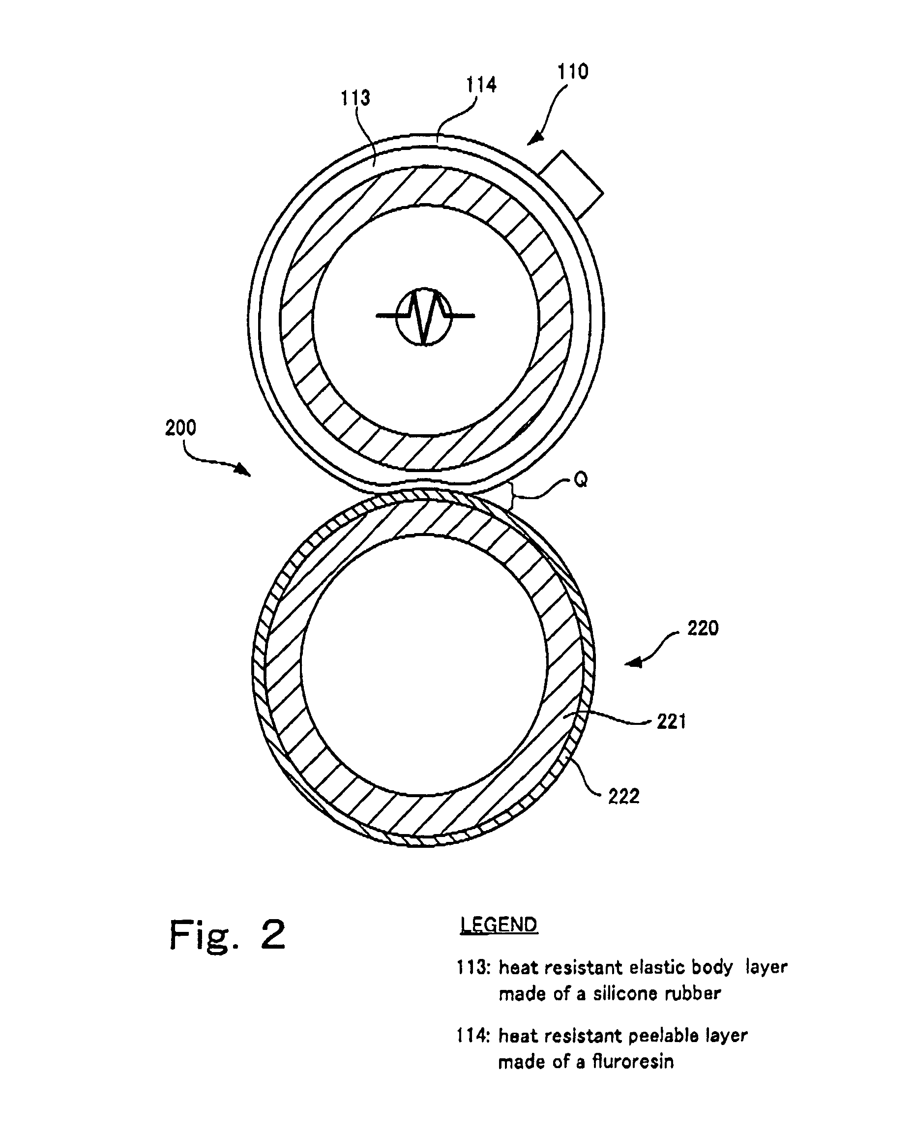
However, this problem is not exclusive in the belt nip type fixing device but possibly arises likewise even in the aforementioned heat roll type fixing device in the case where the resistance of the pressure roll (circulating body) is increased when its surface is circulated.

Method used


Image

  • Circulating body and fixing device
  • Circulating body and fixing device
  • Circulating body and fixing device

Examples


example 1

[0081]In the first example, a fluororesin solution (manufactured by Mitsui•Du Pont Flurochemical) prepared by mixing a PFA powder having an average particle diameter of 8 μm and a low melt viscosity (0.3×10⁴ to 0.5×10⁴ Pa·s; 380° C.) with a PFA dispersion, prepared by dispersing a PFA fine particle having an average particle diameter of. 0.2 μm and a low melt viscosity (0.3×10⁴ to 0.5×10⁴ Pa·s; 380° C.) in an aqueous solvent, in the following ratio: PFA powder / PFA fine particle=15 / 85, is used as the material of the surface layer.

[0082]Also, as the filler particle, barium sulfate (BMH-60, manufactured by Sakai Chemical Industry Co., Ltd.: average particle diameter: 5 μm, and content of a large particle 15 μm or more in size is 2 mass % or less) is used and compounded in an amount of 10 mass parts based on 100 mass parts of PFA.

[0083]Here, the ratio of “PFA powder / PFA fine particle=15 / 85” means that the PFA powder is about 18 mass parts per 100 mass parts of the PFA fine particle. Thi...

example 2

[0086]In the second example, the same material in the first example is used except that zeolite (Toyobuilder (manufactured by Tosoh Corporation), average particle diameter: 2 μm) is used as the filler particle in place of barium sulfate in the first example in an amount of 5 mass parts in 100 mass parts of PFA.

[0087]Here, the proportion of “5 mass parts” of the filler particle is close to the lower limit of the aforementioned preferable proportion, namely, “the amount of the inorganic fine particle is 3 mass parts or more and 15 mass parts or less based on 100 mass parts of the fluororesin”.

[0088]The gloss of the surface layer in the second example is 36 as the value measured by a 75° micro-gloss meter (BYK Gardner). Also, the surface roughness Ra of the surface layer is 0.9 μm and the filtered wave center waviness of the surface layer is 0.58 μm in the condition of a cutoff of 0.25 mm. Further, the static friction coefficient of the surface layer with a common paper at 100° C. is m...

example 3

[0089]In the third example, the same material in the first example is used except that as the filler particle, a mixture of barium sulfate (BMH-60, manufactured by Sakai Chemical Industry Co., Ltd., average particle diameter: 5 μm, large particles having a particle diameter of 15 μm or more is 2 mass % or less) and mica (Iriodin(R) 111 manufactured by Japan Merk Co., Ltd.) is used, and barium sulfate and mica are compounded in an amount of 5 mass parts and in an amount of 3 mass parts respectively based on 100 mass parts of PFA. Namely, in this example, the mixture of plural types of filler materials is used.

[0090]The gloss of the surface layer in the third example is 39 as the value measured by a 75° micro-gloss meter (BYK Gardner). Also, the surface roughness Ra of the surface layer is 1.0 μm and the filtered wave center waviness of the surface layer is 0.45 μm in the condition of a cutoff of 0.25 mm. Further, the static friction coefficient of the surface layer with a common pape...


PUM


Abstract

A circulating body driven with its surface being circulated along a fixed route and having a base material provided with a tubular outside peripheral surface and a surface layer covering the outside peripheral surface of the base material, the surface static friction coefficient of the surface layer is designed to be 0.06 or less with common paper at 100° C.

Description

BACKGROUND OF THE INVENTION[0001]1. Field of the Invention[0002]The present invention relates to a circulating body that is used for a fixing device fixing an unfixed image under heating and pressure in an image forming device such as copiers, printers and facsimile machines and is driven in such a manner that its surface is circulated along a fixed route and also to a fixing device using the circulating body.[0003]2. Background Art[0004]It is usually necessary to form a permanent image by fixing an unfixed toner image formed on a recording sheet in copiers and the like making use of an electrophotographic process. As the fixing method, a solvent fixing method, pressure fixing method and heat fixing method are known. Among these fixing methods, the solvent fixing method has the drawback that solvent vapor is emitted during fixing, giving rise to many problems concerning odors and sanitation. The pressure fixing method has the drawback that it is inferior in fixing characteristics to...

Claims


Application Information

Patent Timeline
Patent Type & Authority Patents(United States)
IPC IPC(8): G03G15/20F16C13/00
CPCG03G15/2057G03G2215/2009
Inventor KOMURO, HITOSHITAMEMASA, HIROSHITSUTSUMI, YOUSUKENAKATOGAWA, KENJIINAMURA, KEI
Owner FUJIFILM BUSINESS INNOVATION CORP
Learn More