

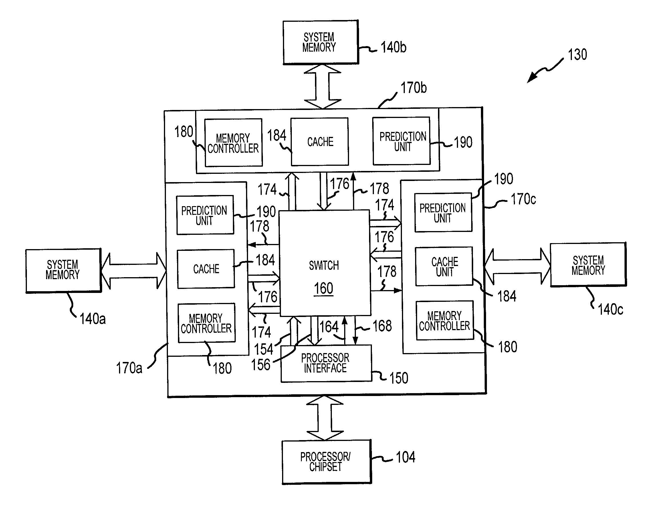
Memory hub with internal cache and/or memory access prediction
a memory hub and hub technology, applied in the field of computer systems, can solve the problems of slow memory hub speed, and inability to maintain the operation speed of processors, and achieve the effect of improving the performance of computer systems and limited performan
- Summary
- Abstract
- Description
- Claims
- Application Information
AI Technical Summary
Benefits of technology
Problems solved by technology
Method used
Image

Examples
Embodiment Construction
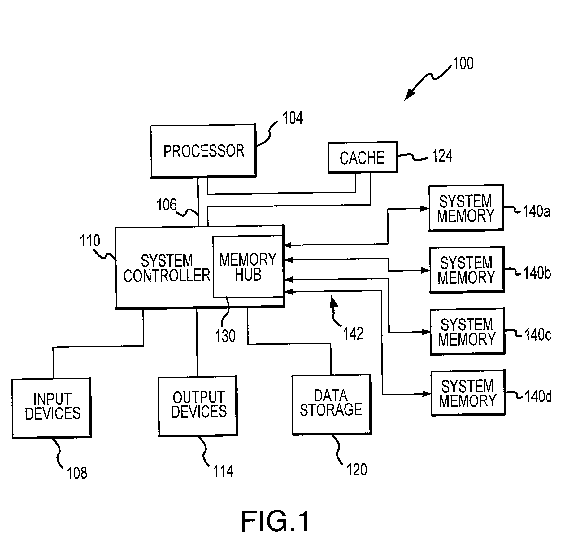
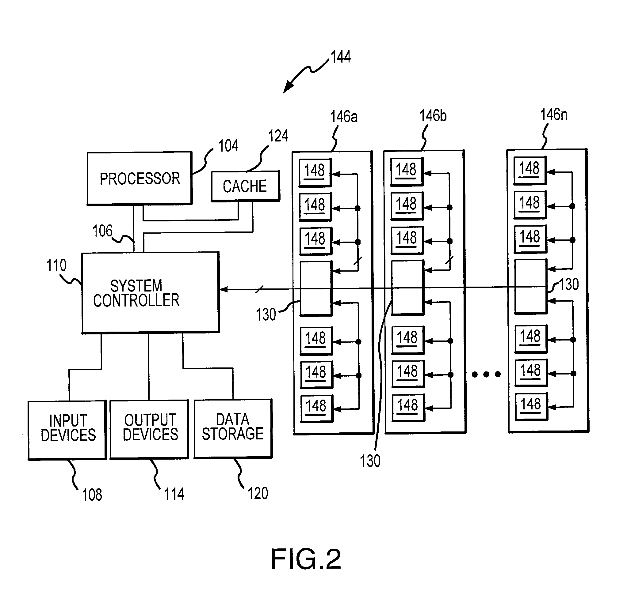
[0011]A computer system 100 according to one embodiment of the invention is shown in FIG. 1. The computer system 100 includes a processor 104 for performing various computing functions, such as executing specific software to perform specific calculations or tasks. The processor 104 includes a processor bus 108 that normally includes an address bus, a control bus, and a data bus. In addition, the computer system 100 includes one or more input devices 108, such as a keyboard or a mouse, coupled to the processor 104 through a system controller 110 to allow an operator to interface with the computer system 100. Typically, the computer system 100 also includes one or more output devices 114 coupled to the processor 104 through the system controller 110, such output devices typically being a printer or a video terminal. One or more data storage devices 120 are also typically coupled to the processor 104 through the system controller 110 to allow the processor 104 to store data or retrieve...
PUM
 Abstract
Description
Claims
Application Information