Apparatus to treat and inspect a substrate

a technology for treating and inspecting substrates, applied in the field of environmental control, can solve the problems of attracting atmospheric contaminants to the treated substrates, condense or “rain out” of contaminants contained therein, and potential device damage, so as to reduce clogging and sputtering, prevent contamination of the substrate, and increase the effect of joule-thompson cooling

Inactive Publication Date: 2006-11-14
COOL CLEAN TECH
View PDF21 Cites 31 Cited by
  • Summary
  • Abstract
  • Description
  • Claims
  • Application Information

AI Technical Summary

Benefits of technology

[0010]The apparatus of the present invention includes a protective enclosure within which is positioned a cryogenic fluid applicator for treating and inspecting a substrate placed therein. The protective enclosure is partially open to the atmosphere and includes a filtered air circulation system and ionization mechanism to provide for a partially-pressurized, heated and ionized re-circulated atmosphere within the protective enclosure to prevent contamination of the substrate. The re-circulated atmosphere flows at a controlled velocity in a manner consistent with the geometry of the cavity and substrate being treated so as not to produce undue turbulence and erratic flow lines within the cavity. The substrate may be held within the cavity by means of a vacuum fixture, operator hands or other suitable fixture. Alternatively, the substrate may be inserted within the partial enclosure, treated and removed using an external robot or conveyed through each side using an automated track.
[0011]The present invention further includes a snow generation system connected to the cryogenic fluid applicator. The snow generation system includes a stepped capillary condenser having at least two connected segments of tubing with differing diameters to provide increased Joule-Thompson cooling in the conversion of liquid carbon dioxide to solid carbon dioxide, which reduces clogging and sputtering, improves jetting, and allows for greater spray temperature control. Moreover, the stepped capillary condenser produces coarser particles than a single step capillary.

Problems solved by technology

This rapidly lowers local ambient atmospheric temperature causing contaminants contained therein to condense or “rain-out” of the local atmosphere and onto treated substrate surfaces during or following spray treatments.
This presents problems including, for example, potential device damage from electrostatic overstress or electrostatic discharge, and attraction of atmospheric contaminants to treated substrates via electrostatic attractive forces.
However, the approach of the '384 patent does not work well for most substrate treatment applications because many materials being cleaned, or at least portions thereof, have low thermal conductivity, low mass or because highly thermal conductive materials rapidly lose heat to the sublimating snow during impact.
This tends to create localized cold spots on even a mostly hot bulk substrate.
Additionally, many electromechanical devices being cleaned are relatively small, providing no appreciable mass for storing heat.
Moreover, contact of the ionizing gas with the stream prior to contact with the surface rapidly eliminates ion concentration and is ineffective in controlling electrostatic dishcarge.

Method used


Image

  • Apparatus to treat and inspect a substrate
  • Apparatus to treat and inspect a substrate
  • Apparatus to treat and inspect a substrate

Examples


Embodiment Construction

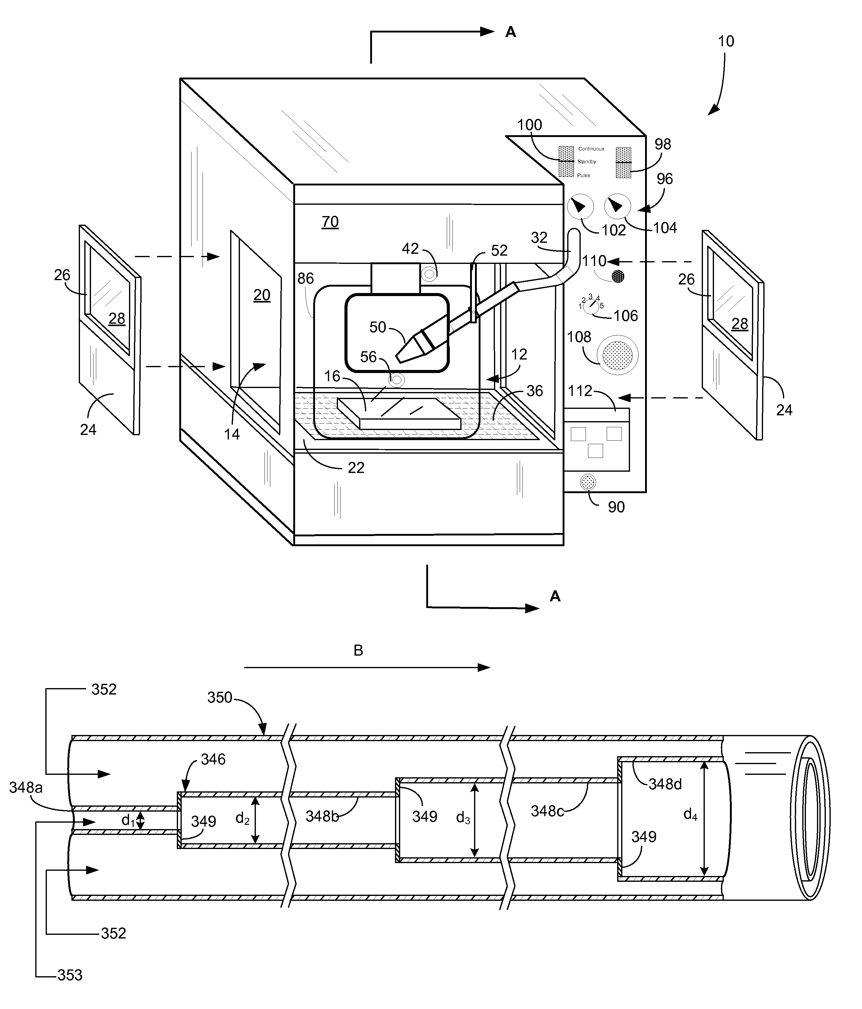
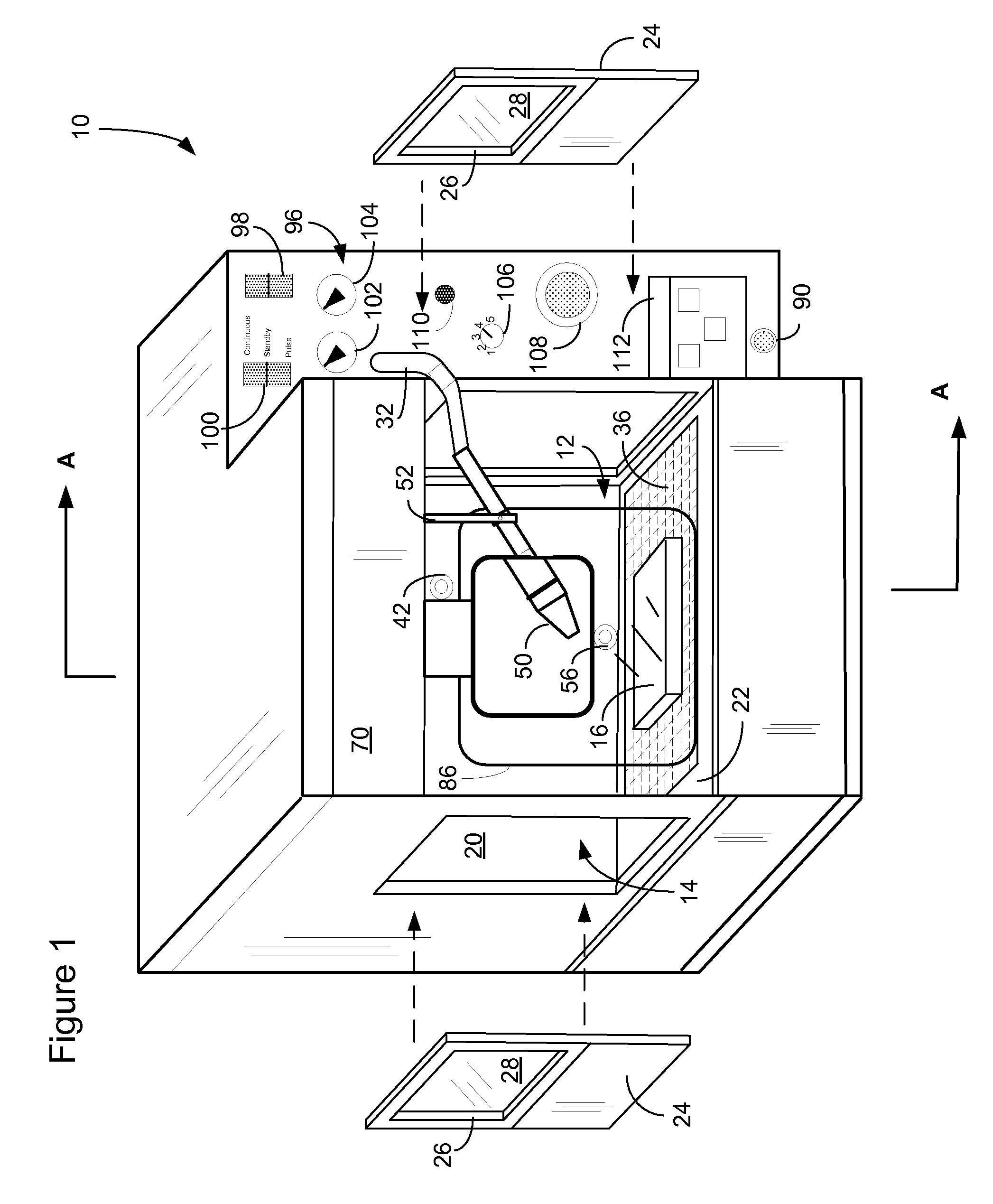
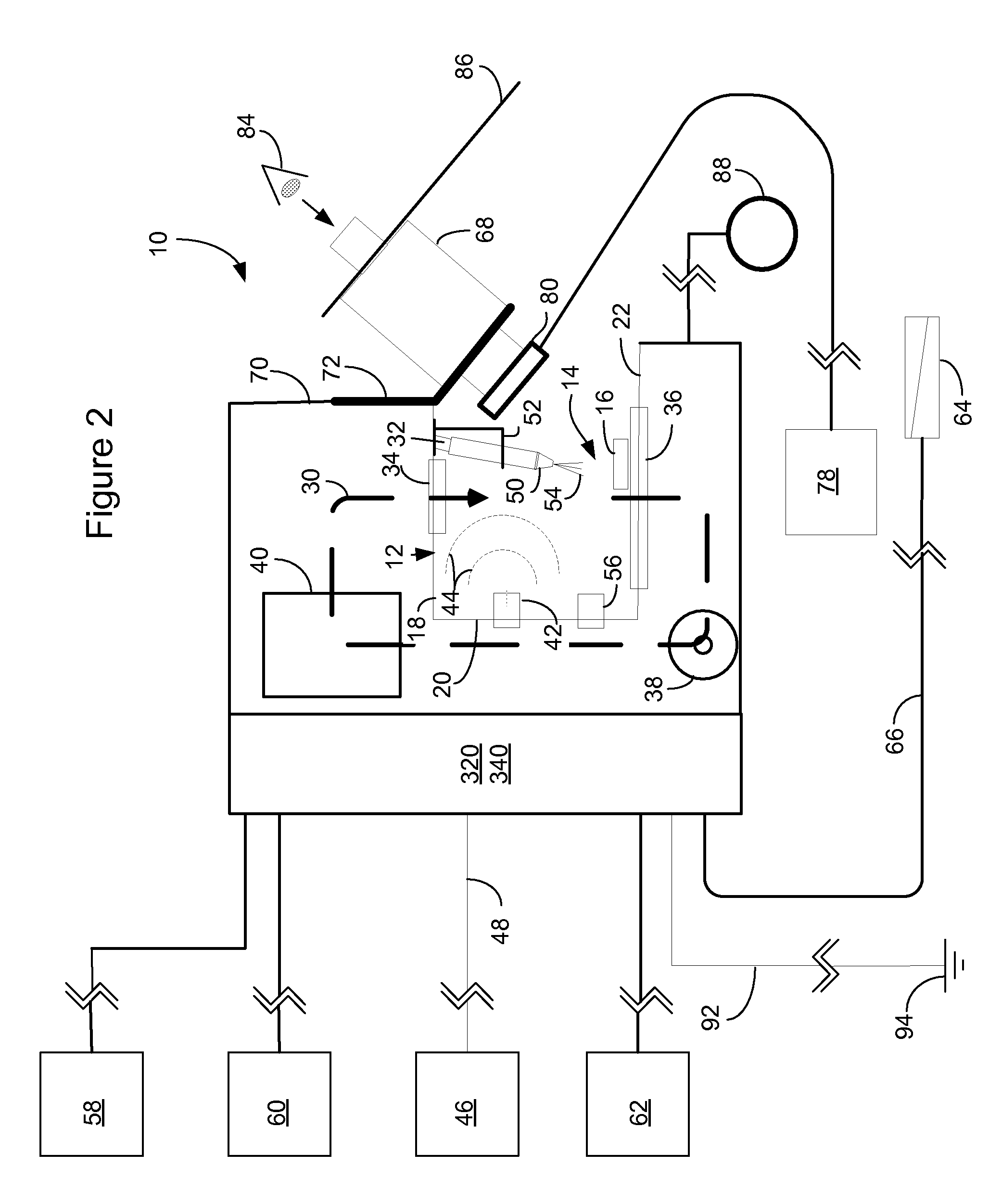
[0019]An apparatus to selectively treat and inspect a substrate is generally indicated 10 in FIGS. 1 and 2. The apparatus 10 includes a protective enclosure 12 which defines a mini-environment or cavity 14 for providing an instantaneous curtain or sheath of re-circulated and controlled atmosphere when treating or inspecting substrates 16 positioned therein. The protective enclosure 12 includes a ceiling, 18 walls 20, base 22 and removable electrostatic-discharge dissipative side panels 24, all of which provide a partial enclosure about the substrate 16 during processing and thus forming the cavity 14 therein. Each side panel 24 includes an upper aperture 26 containing a pane of transparent material 28 to allow further lighting within the cavity 14. The protective enclosure 12 is designed to have a portion open to the ambient atmosphere for insertion of the substrate 16 to be treated. The enclosure 12 may be constructed of any variety of materials including, but no limited to, metals...


PUM


Abstract

An apparatus for treating a substrate with a cryogenic impingement fluid includes a protective enclosure defining an internal cavity, a cryogenic fluid applicator positioned within the internal cavity and a snow generation system connected to the cryogenic fluid applicator. The snow generation system includes a condensing subsystem and a diluent or propellant gas subsystem. Each subsystem is connectable to a common gas source. The condensing subsystem includes a condenser for condensing liquid carbon dioxide into solid carbon dioxide particles, or dry ice snow. The condenser includes at least two segments of differing diameter connected to one another. Liquid carbon dioxide is introduced into the smaller diameter first segment and upon entering the larger diameter second segment, solidifies into dry ice particles. The dry ice particles, along with diluent or propellant gas produced from the diluent subsystem, are delivered to the cryogenic fluid applicator via a coaxial delivery tube.

Description

CROSS-REFERENCE TO RELATED APPLICATION(S)[0001]This application claims the benefit U.S. Provisional Patent Application No. 60 / 635,400 entitled MEHTOD AND APPARATUS FOR SELECTIVELY TREATING AND INSPECTING A SUBSTRATE filed on 13 Dec. 2004 which is hereby incorporated herein by reference.BACKGROUND OF INVENTION[0002]The present invention generally relates to the field of environmental control for performing cryogenic spray cleaning processes. More specifically, the present invention is directed at cleaning or treating miniature electromechanical device surfaces with cryogenic impingement sprays.[0003]Conventional precision cleaning processes using cryogenic particle impingement sprays, such as solid phase carbon dioxide, require control of the atmosphere containing a treated substrate to prevent the deposition of moisture, particles or other such contaminants onto surfaces during and following cleaning treatments. Environmental control is required because of localized atmospheric pert...

Claims


Application Information

Patent Timeline
Patent Type & Authority Patents(United States)
IPC IPC(8): B24C3/12
CPCB24C1/003B24C5/02B24C9/00Y10S134/902
Inventor JACKSON, DAVID P.
Owner COOL CLEAN TECH
Why Eureka
Try Eureka