Optical fibre-based devices utilising the Raman effect

a technology of optical fibre and raman, which is applied in the direction of fiber transmission, lasers, transmission, etc., can solve the problems of interference with co-propagating signals, major loss and noise, and the length of fibre required in standard fibre raman devices is rayleigh back-scatter, so as to increase the nonlinearity of holey fibres and increase the raman gain. , the effect of increasing the power handling capability

Inactive Publication Date: 2006-11-14
UNIV OF SOUTHAMPTON
View PDF7 Cites 33 Cited by
  • Summary
  • Abstract
  • Description
  • Claims
  • Application Information

AI Technical Summary

Benefits of technology

[0012]Holey optical fibre has a much greater nonlinearity than the standard optical fibre used in such Raman devices, typically between ten and a hundred times higher for silica fibre. This means that a useful and beneficial level of optical gain or loss can be achieved via the Raman effect in holey fibre by using a much shorter length of fibre than is required to provide the same amount of gain or loss from a standard fibre. For example, device lengths as short as tens of meters or less are possible using holey fibre, compared with typically 10 km lengths of conventional fibre. Thus, it is expected that Rayleigh backscattering will be significantly reduced by making use of holey fibre as a Raman gain medium.
[0055]launching the light at the first wavelength and the light at the second wavelength into a holey optical fibre with a structure which allows the fibre to guide light at a first wavelength and a second longer wavelength and which results in energy transfer of the light at the first wavelength to the second wavelength by the nonlinear optical process of Raman scattering within the fibre and hence provides optical loss at the first wavelength which varies in time, so that the light at the first wavelength experiences the varying optical loss and is modulated.

Problems solved by technology

A particular problem associated with the long fibre lengths required in standard fibre Raman devices is Rayleigh back-scatter.
Propagating light at all wavelengths is scattered in a backwards direction from small-scale irregularities in the glass from which the fibre is made; further, the backscattered light can itself be scattered (double Rayleigh backscatter), and then interferes with the co-propagating signal.
This is a major source of loss and noise, and increases with fibre length, as more scattering incidents can occur in the course of propagation.

Method used


Image

  • Optical fibre-based devices utilising the Raman effect
  • Optical fibre-based devices utilising the Raman effect
  • Optical fibre-based devices utilising the Raman effect

Examples


first embodiment

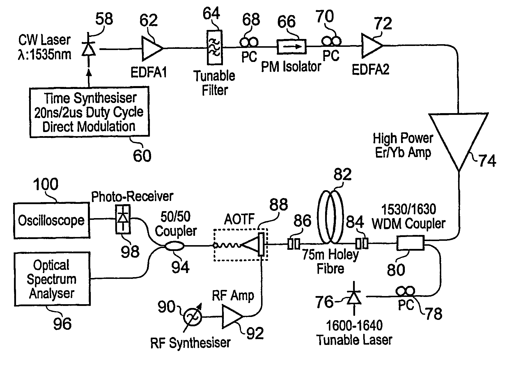
[0115]FIG. 12 shows a schematic diagram of an experimental setup used to implement a Raman amplifier using holey fibre in accordance with a first embodiment of the present invention. A co-propagation scheme of pump and signal was adopted (in which the pump wave and the signal, or probe, wave are launched into the same end of the holey fibre) so as to avoid difficulties of having to maximise the launching of light into the holey fibre at both of its ends.

[0116]A pump optical source 58 is used to provide pump light. The pump optical source 58 is a quasi-cw pulsed source capable of generating 20 ns square pulses of 500 kHz, by use of an associated time synthesiser 60 to modulate the output of a semiconductor laser. This arrangement gives watts of peak power, which is sufficient to obtain an appreciable level of gain. The use of such short pulses, having a 500 ps rise time, broadens the spectral bandwidth of the pump pulses, which helps to minimise the unwanted effect of stimulated Bril...

second embodiment

[0129]As discussed in the Theoretical Background section, the Raman effect can provide optical loss, as well as optical gain [3, 12]. This can be used to modulate an optical signal, whereby the pattern of a modulated pump wave is imprinted “negatively” onto a cw signal wave at a shorter wavelength and weaker power; “holes” are effectively made in the signal wave by the loss induced by the pump wave. Using holey fibre as the Raman medium in such a device confers the same benefits as are obtained by using a holey fibre in a Raman amplifier, such as a much reduced fibre length to produce a similar effect compared to a device based on standard fibre.

[0130]FIG. 18 shows a schematic diagram of an experimental arrangement used to provide an optical modulator based on the Raman effect in a holey fibre according to a second embodiment of the invention. The components are the same as those used for the Raman amplifier described in the first embodiment, with reference to FIG. 13, except that t...

third embodiment

[0141]The benefits of using a holey fibre as a Raman medium can be further exploited by using holey fibre as the gain medium in a Raman laser. In a Raman laser, the gain derives from stimulated Raman scattering, as described above with respect to the Raman amplifier, and the output signal at the Stokes wavelength derives initially from the first scattering events producing photons at the Stokes wavelength. It is further increased by the provision of optical feedback to provide multiple passes through the Raman gain medium so that the Stokes wave experiences the Raman gain, is amplified, and lases. Thus, as for conventional fibre amplifiers and lasers, a Raman fibre laser differs from a Raman fibre amplifier by including a feedback arrangement and not having an optical source at the output wavelength.

[0142]FIG. 22(a) shows a possible configuration for a Raman fibre laser based on a holey fibre. The laser is arranged as a bulk device in a Fabry-Perot configuration. A pump source 112 p...


PUM

PropertyMeasurementUnit
lengthaaaaaaaaaa
lengthaaaaaaaaaa
lengthaaaaaaaaaa

Abstract

An optical fibre device based on the Raman effect comprises a first optical source to provide light at a first wavelength, and a holey optical fibre which receives the light from the first optical source such that optical gain or loss is provided at a second wavelength by the effect of Raman scattering within the fibre. For optical gain, the second wavelength is longer than the first wavelength, and the device can be operated as an amplifier, or as a laser if optical feedback is provided. For optical loss, the second wavelength is shorter than the first, and the device may be used as an optical modulator. The fibre may be fabricated from pure silica, although other undoped or doped materials may alternatively be used to tailor properties of the fibre such as gain spectrum, bandwidth, power handling capability and mode propagation.

Description

[0001]This application is a national phase of International Application No. PCT / GB02 / 04400 filed Sep. 27, 2002 and published in the English language.BACKGROUND OF THE INVENTION[0002]The present invention relates to optical fibre-based devices which utilise Raman scattering. In particular, the devices include optical amplifiers, optical modulators and lasers.[0003]The capability of silica optical fibres to carry large amounts of information over long repeaterless spans in telecommunications systems makes lightwave communications very attractive. Numerous channels at different wavelengths can be multiplexed on the same fibre to maximise the use of the available bandwidth. Higher transmission powers and / or lower loss fibres can increase system margins.[0004]A device commonly used to compensate for the losses in fibre is the erbium-doped fibre amplifier (EDFA). This is based on silica fibre doped with erbium, which, when pumped with light of a suitable wavelength, provides optical gain ...

Claims


Application Information

Patent Timeline
Patent Type & Authority Patents(United States)
IPC IPC(8): G02B6/032G02F1/365
CPCG02F1/365G02F2202/32
Inventor YUSOFF, ZULFADZLIBELARDI, WALTERTEH, PEH CHIONGLEE, JU HANMONRO, TANYA MARYRICHARDSON, DAVID JOHN
Owner UNIV OF SOUTHAMPTON
Why Eureka
Try Eureka