Liquid crystal display device having an improved lighting device

a liquid crystal display device and lighting technology, applied in the direction of instruments, light sources, optics, etc., can solve the problems of non-uniform display image, display non-uniformity described above, and difficulty in increasing the display brightness of the isp type liquid crystal display devi

Inactive Publication Date: 2006-11-21
PANASONIC LIQUID CRYSTAL DISPLAY CO LTD +1
View PDF28 Cites 135 Cited by
  • Summary
  • Abstract
  • Description
  • Claims
  • Application Information

AI Technical Summary

Benefits of technology

[0016]An object of the present invention is to provide a liquid crystal display device by which brightness of an image displayed on a liquid crystal display panel (a liquid crystal display element) mounted thereon is efficiently improved, and various problems associated with heat generation of a light source for illuminating the liquid crystal display panel with light are solved.

Problems solved by technology

However, when a temperature of the liquid crystal cell locally rises, the light transmission of the liquid crystal cell varies in that portion according to the change in the refractive index of the liquid crystal molecule present in that portion, and therefore, non-uniformity occurs in the display image.
Accordingly, the light transmission of a part of the liquid crystal cell fails to correspond to the electric field applied to the liquid crystal molecules, and the display non-uniformity described above occurs.
This problem often occurs, as compared with a liquid crystal display device of a twisted nematic type (TN type), in a vertical alignment type (VA type) in which a temperature at which the liquid crystal layer becomes isotropic is low (which is called a transition temperature of liquid crystal material or a transition temperature), or in a liquid crystal display device of the horizontal electric field type (the in-plane-switching type, or the ISP type).
Therefore, it is difficult to increase the display brightness of the ISP type liquid crystal display device.
Further, in a case where the technique of adjusting the brightness of a light source for every image formed by moving picture signals is applied to the liquid crystal display device, setting of timing for reduce a large lamp current of the light source for the wholly bright image to the reference current is difficult in practical use.
In other words, even if this technique is applied to the liquid crystal display device, in a case where an image whose brightness rarely varies for a given period (a period in which a plurality of image data are transmitted to the liquid crystal display device) such as a static image is displayed, the contrast ratio cannot be enhanced.
However, even if these publications are referred to, it is difficult to find the conditions for adequately setting switching timing of the lamp current.

Method used


Image

  • Liquid crystal display device having an improved lighting device
  • Liquid crystal display device having an improved lighting device
  • Liquid crystal display device having an improved lighting device

Examples


Embodiment Construction

[0058]In any of the above-described liquid crystal display devices, it is possible to solve the problems that are intended to be solved by the present invention and other various problems, details of which will be described with reference to the embodiment of the present invention.

[0059]The specific embodiments of the present invention will be described hereinafter with reference to the drawings associated therewith. In the drawings referred to in the following description, parts having the same function are indicated by the same reference numerals, repeated description of which is omitted.

>

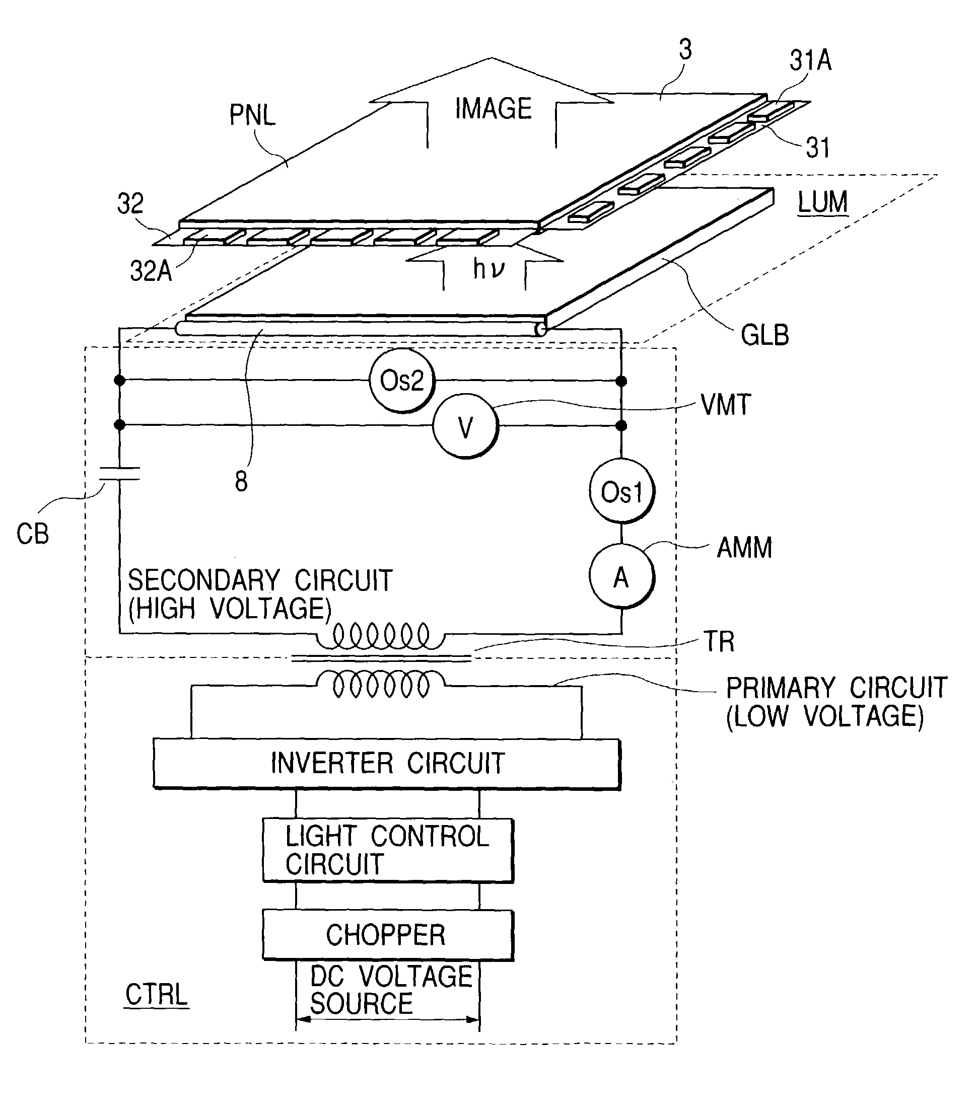
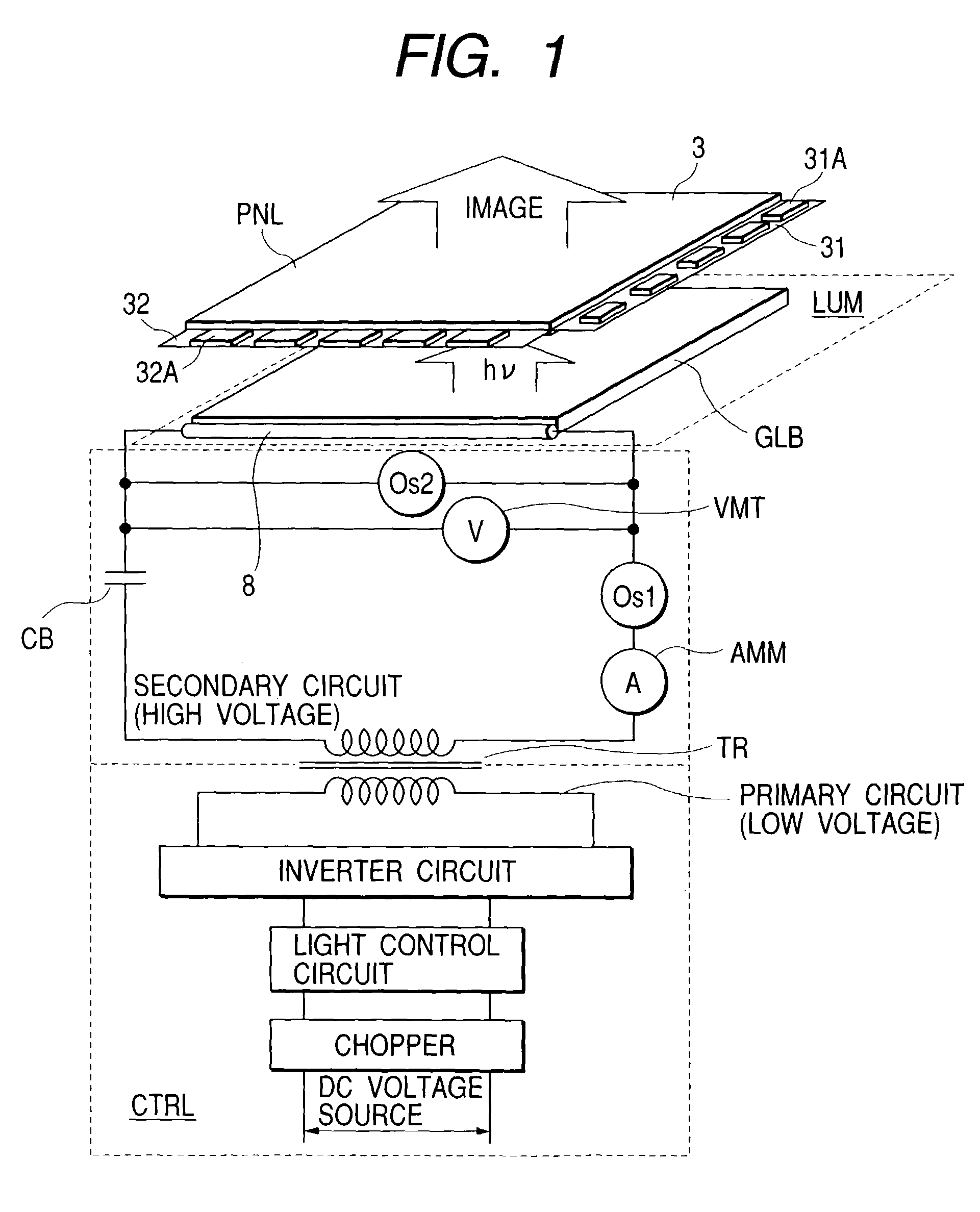
[0060]FIG. 1 shows constituent elements related to the present invention in one example of the liquid crystal display device.

[0061]A liquid crystal display panel (a liquid crystal display element) used for an image display of a liquid crystal display device is provided with a pair of substrates 3 arranged opposite to each other, a liquid crystal layer (not shown) sealed between the substrates, an...


PUM

PropertyMeasurementUnit
temperatureaaaaaaaaaa
peak voltageaaaaaaaaaa
thicknessaaaaaaaaaa

Abstract

A liquid crystal display device includes a liquid crystal display panel having plural pixels, a lighting device having at least one light source and projecting light generated by the light source on the liquid crystal display panel, and a circuit supplying a first current during a first period and a second current smaller than the first current during a second period to the light source alternately. The circuit includes a current monitoring circuit which measures the first current and the second current, and a light control circuit which adjusts a ratio of the first period to the second period based upon a signal from the current monitoring circuit.

Description

[0001]This application is a continuation application of U.S. application Ser. No. 09 / 934,696 filed on Aug. 23, 2001 now U.S. Pat. No 6,636,190.BACKGROUND OF THE INVENTION[0002]The present invention relates to a liquid crystal display device, and relates to a light source suitable for efficiently enhancing a brightness of a display screen and making it uniform over the entire display screen area, and a control method therefor.[0003]A display device using a liquid crystal display element (also called a liquid crystal display panel), an electroluminescent element (which is divided into an organic system and an inorganic system depending on a fluorescent material used, hereinafter referred to as an EL element), a field emission device (hereinafter referred to as an FE element) or the like displays an image without requiring a space (a vacuum envelope) for scanning an electron beam two-dimensionally on the back of the display screen as in a cathode ray tube (CRT). Accordingly, these disp...

Claims


Application Information

Patent Timeline
Patent Type & Authority Patents(United States)
IPC IPC(8): G09G3/36G02F1/1335G02F1/133G02F1/13357G09G3/20G09G3/34H05B41/392
CPCG02F1/133604G09G3/342H05B41/3927H05B41/2821H05B41/2824G02F2001/133612G09G2310/024G09G2320/0261G09G2320/041G09G2320/064G09G2320/066G09G2330/045G09G2320/0633G02F1/133612G02F1/133
Inventor HIRAKATA, JUNICHIONO, KIKUOSHINGAI, AKIRA
Owner PANASONIC LIQUID CRYSTAL DISPLAY CO LTD
Why Eureka
Try Eureka