Hydraulic impulse generator and frequency sweep mechanism for borehole applications

a technology of frequency sweep mechanism and impulse generator, which is applied in the direction of survey, instruments, borehole/well accessories, etc., can solve the problems of in-line configuration extremely complex, difficult to manufacture and assemble, and dynamic instability of the poppet valv

Active Publication Date: 2006-11-21
WELLS FARGO BANK NAT ASSOC +1
View PDF18 Cites 121 Cited by
  • Summary
  • Abstract
  • Description
  • Claims
  • Application Information

AI Technical Summary

Benefits of technology

[0031]A first aspect of the present invention is directed to a flow pulsing apparatus that generates negative pressure pulses of substantial magnitude downstream of at least a partially interrupted fluid flow within a conduit. Preferably, the at least partial interruption of fluid flow occurs without generating an upstream positive pressure pulse or water hammer pulse associated with prior art flow pulsing apparatus. In at least one embodiment, the upstream positive pressure pulse is avoided by providing a valve configuration that enables an incompressible fluid to continually flow into the valve through an inlet port and subsequently flow from the valve through an outlet port or through a drain port that empties into the conduit above the valve. The rapid reduction or total interruption of flow of the pressurized fluid through the valve outlet produces the negative pressure pulse.
[0032]The valve includes a first member configured to be actuated by the pressurized fluid to cycle between an open position and a closed position, such that when in the closed position, the first member at least partially interrupts the flow of the pressurized fluid through an outlet. The valve also includes a second member that is disposed within the first member. The second member is configured to be reciprocated back and forth between first and second positions during each cycle by the pressurized fluid, such that a position of the second member controls the timing of the valve. Preferably, the first and second member are disposed coaxially. Because the second member is disposed within the first member, flow paths between the first and second member are extremely short and direct.
[0033]The first member is fitted with bushings at each end to capture the second member and to limit its travel inside the first member. The first member travels axially inside of two end rings, disposed near each end of the first member. As the first and second members travel from one position to the next, fluid passages within the valve are opened and closed by grooves and openings in the first and second members. The size and location of the openings and grooves control the timing of the valve. In at least one embodiment the entire valve mechanism is housed in a single cartridge that is installed with a stab-type seal in a special housing above a bit. The cartridge can be configured to include fluid channels that enable at least a portion of the interrupted flow of fluid to be diverted back up the drillstring, to reduce a water hammer effect. The larger the volume of the flow of pressurized fluid that is diverted, the greater the reduction in the water hammer effect that is achieved. In some applications, the water hammer effect is beneficial, and thus, the present invention encompasses both embodiments in which fluid channels are configured to divert sufficient pressurized fluid so that the water hammer effect is substantially minimized, and embodiments in which little or no pressurized fluid is diverted, so that the water hammer effect is not substantially reduced.

Problems solved by technology

The poppet valve is dynamically unstable; when closed, it is energized to open, and when open, it is energized to close.
The pilot spool is also dynamically unstable.
While functional, the in-line configuration is extremely complex and is correspondingly difficult to manufacture and assemble.
The housings are difficult to align, and the seal elements between the housings are prone to premature failure, particularly in the unforgiving environment associated with drilling operations.
The long, interconnecting fluid passages and cross-drilled holes are subject to rapid erosion by the drilling mud at each change of flow direction.
The valve is also subject to large pressure drops due to fluid friction through the long, complex passages.
The bit creates acoustic noise as it bounces and scrapes against the rock.
Current SWD techniques, which employ the drill bit as a source, provide seismic profiles that are helpful in detecting abnormal pressure trends, but do not provide a look-ahead capability.
Drag bits (representing about 80 percent of offshore drilling) do not create a useable seismic signal, while tricone bits do not create a useful signal in soft formations.
Furthermore, roller cone bits only produce a dipole radiation pattern along the axis of the drillstring, which limits the placement of seismic receivers to locations near the drill rig (a seismically noisy area due to pumps and other rig activity) and restricts the use of bit seismic techniques to vertical wells where the target formations occur in planes perpendicular to the borehole axis.
Deep drilling operations are subject to blowouts when formation pressures become greater than the pressure of drilling fluids in the borehole.
In many formations and under common operating conditions, tricone bits do not generate a signal-to-noise ratio that is usable for SWD.
In particular, the drill bit seismic signal is limited to relatively low frequencies (under 80 Hz) and is incoherent, requiring significant post-processing.
At a frequency of 80 Hz, the depth resolution in a 3 km / s formation is 37.5 meters (approximately four 9-meter joints of drill pipe), which is not useful to drillers.
Significantly, the apparatus described in the Farr patent requires an interruption in the drilling process to actuate the tool.
Seismic receivers must therefore be located near the drill rig, which is a source of substantial masking of seismic noise.
All of these options interrupt the drilling process and increase the potential for borehole instability.
Frequent drilling interruptions would not be an acceptable practice for most operators.
Prior art SWD techniques result in low signal-to-noise ratios, and the resulting signals require substantial processing and interpretation.

Method used


Image

  • Hydraulic impulse generator and frequency sweep mechanism for borehole applications
  • Hydraulic impulse generator and frequency sweep mechanism for borehole applications
  • Hydraulic impulse generator and frequency sweep mechanism for borehole applications

Examples


Embodiment Construction

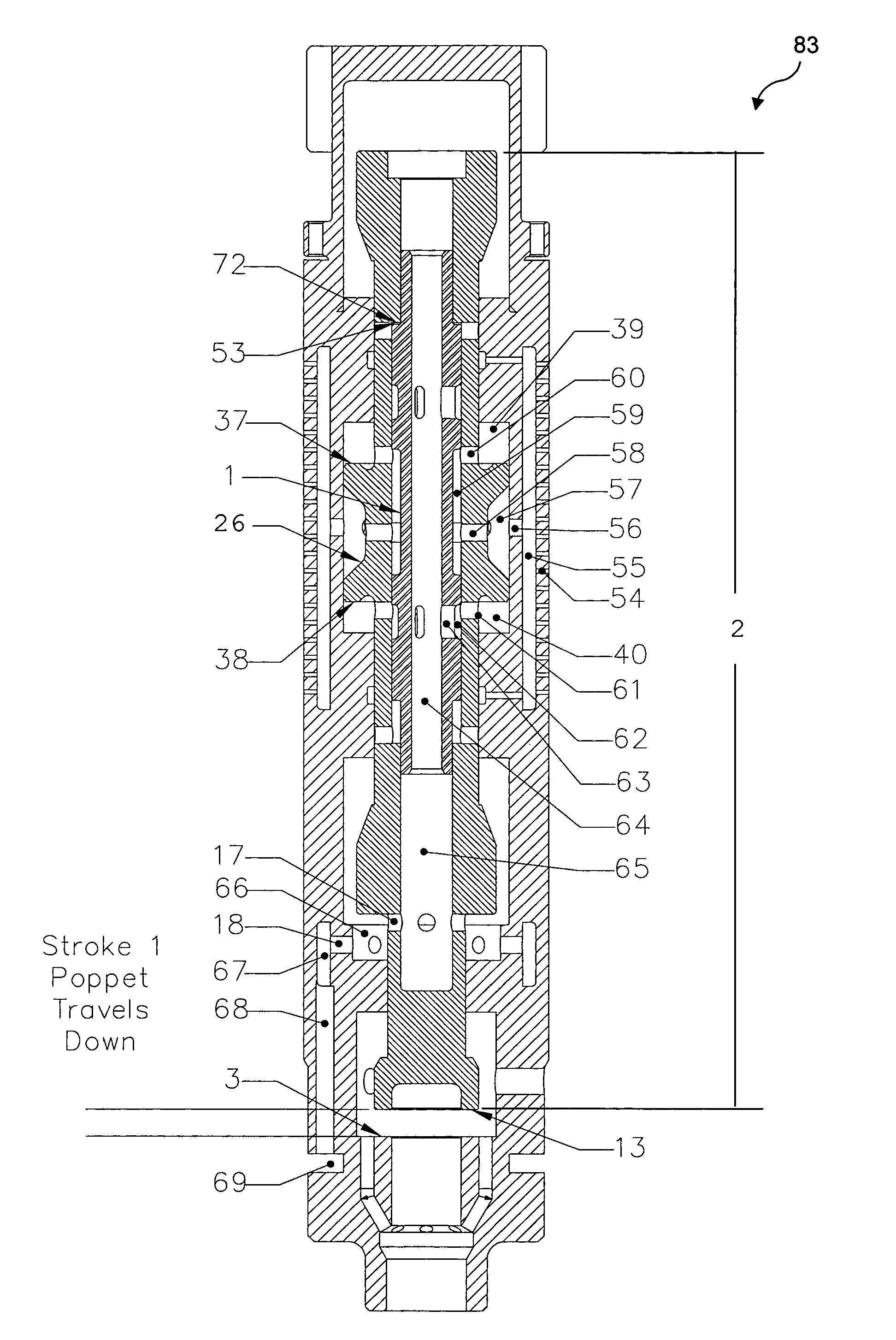
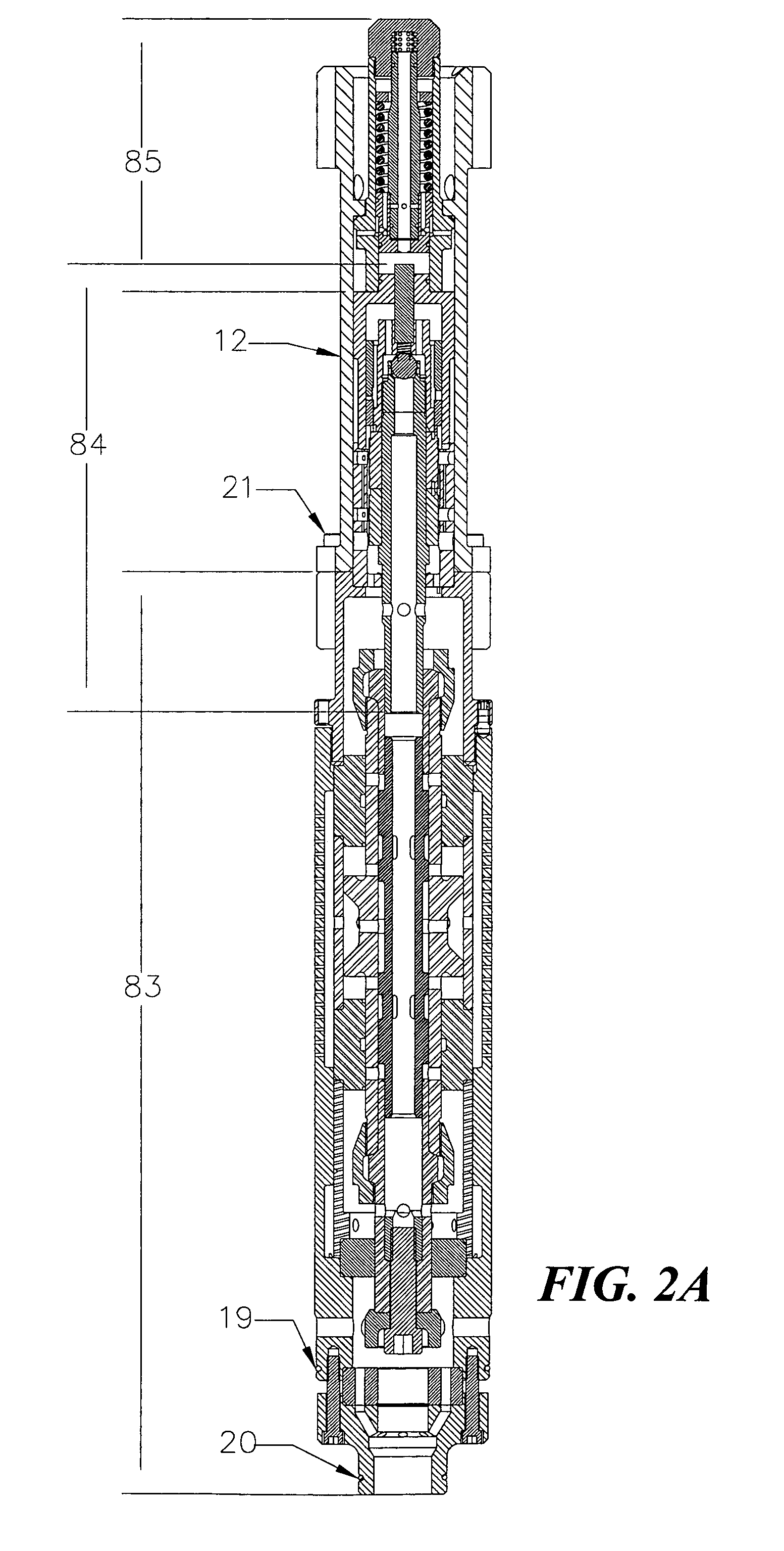
[0092]The present invention is both an improved hydraulic impulse generator and a frequency modulator that is usable with the hydraulic impulse generator to enable a broad range of frequencies to be generated during drilling, to achieve SWD with look ahead imaging. The text that follows first describes the improved hydraulic impulse generator and then describes the frequency modulator that can be used with the improved hydraulic impulse generator to achieve SWD. As noted above, an earlier design of a hydraulic impulse generator is described in commonly assigned U.S. Pat. No. 6,237,701, issued on May 29, 2001. The present invention corrects several problems with this earlier design, as discussed above under the Background of the Invention.

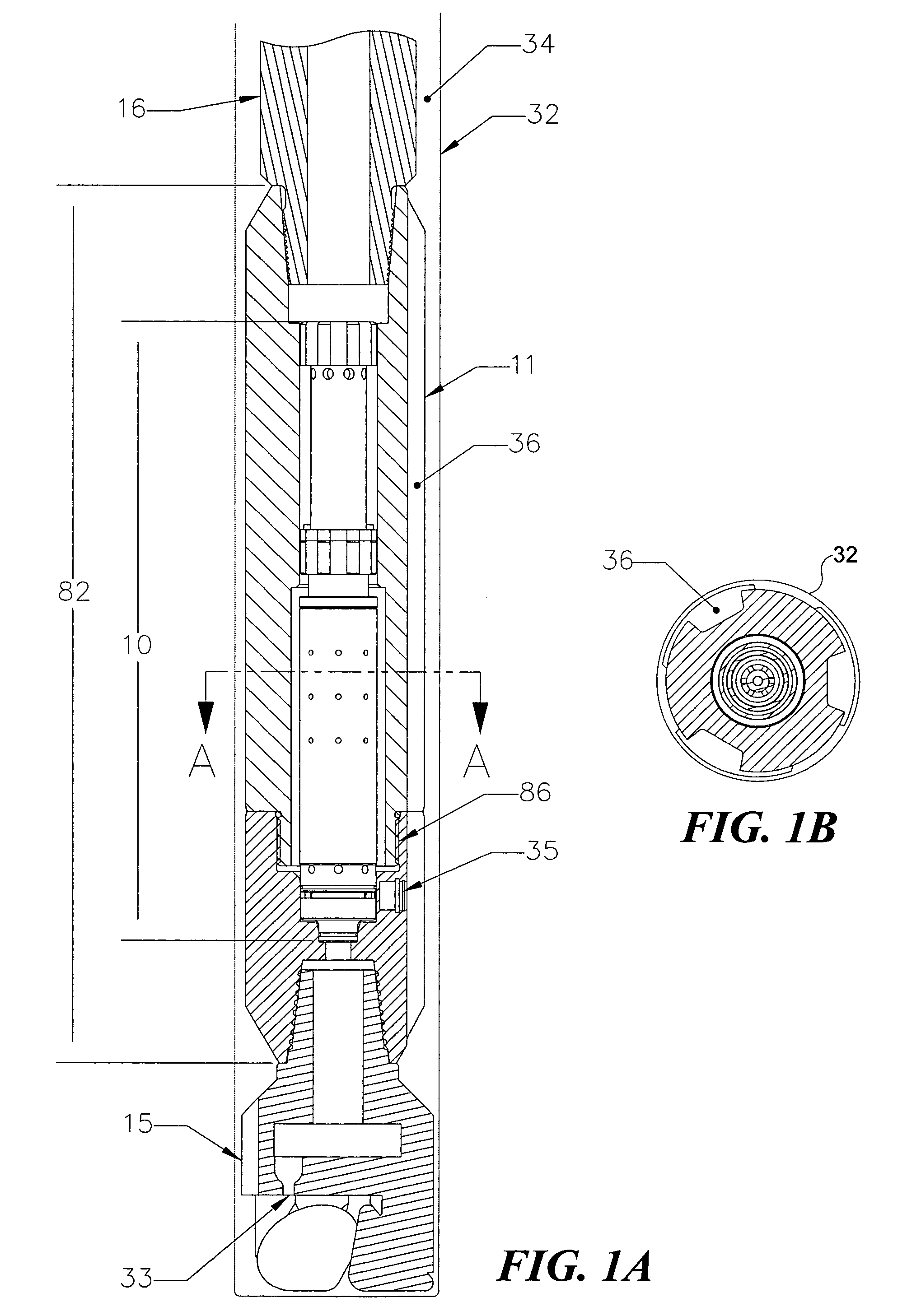
[0093]FIGS. 1A and 1B show the basic configuration of the improved hydraulic impulse generator, which is disposed at the bottom of a rotary drillstring 16. A hydraulic impulse generator 82 is part of a BHA of rotary drillstring 16, which is disposed...


PUM


Abstract

This invention discloses a valve that generates a hydraulic negative pressure pulse and a frequency modulator for the creation of a powerful, broadband swept impulse seismic signal at the drill bit during drilling operations. The signal can be received at monitoring points on the surface or underground locations using geophones. The time required for the seismic signal to travel from the source to the receiver directly and via reflections is used to calculate seismic velocity and other formation properties near the source and between the source and receiver. This information can be used for vertical seismic profiling of formations drilled, to check the location of the bit, or to detect the presence of abnormal pore pressure ahead of the bit. The hydraulic negative pressure pulse can also be used to enhance drilling and production of wells.

Description

GOVERNMENT RIGHTS[0001]This invention was made with U.S. Government support under Contract Nos. DE-FC26-97FT34367 and DE-FG03-00ER83111 awarded by the Department of Energy, and the government may have certain rights in this invention.FIELD OF THE INVENTION[0002]This invention generally relates to an apparatus and a method for interrupting the flow of a fluid within a borehole, and more specifically, to a valve and to a method for interrupting the flow of a incompressible liquid (e.g., drilling mud) through a drillstring in a borehole to generate a negative pressure pulse, and to applications for the negative pressure pulse that is thus generated.BACKGROUND OF THE INVENTION[0003]Numerous references describe tools located above a drill bit in a drillstring for periodically interrupting all or most of the drilling fluid flow to the bit. These tools fall into three general categories, based on their intended application. In the first category are hammer drills that periodically divert d...

Claims


Application Information

Patent Timeline
Patent Type & Authority Patents(United States)
IPC IPC(8): E21B21/10E21B33/12E21B47/14E21B47/18G01V1/00G01V1/40G01V1/42
CPCE21B47/14E21B47/185G01V1/003G01V1/40E21B47/22Y10T137/2552
Inventor KOLLE, JACK J.MARVIN, MARK H.THEIMER, KENNETH J.
Owner WELLS FARGO BANK NAT ASSOC
Why Eureka
Try Eureka