Layered sheet construction for wastewater treatment

a wastewater treatment and layered technology, applied in biological water/sewage treatment, filtration separation, separation processes, etc., can solve the problems of hygienic problems, installation and operation of plants using such processes, and large equipment requirements, and achieve easy and economical manufacturing, reduce the amount of microorganisms on the surface of the layer, and contribute to the durability of the apparatus.

Active Publication Date: 2006-11-28
3M INNOVATIVE PROPERTIES CO
View PDF78 Cites 47 Cited by
  • Summary
  • Abstract
  • Description
  • Claims
  • Application Information

AI Technical Summary

Benefits of technology

[0008]The present invention provides an apparatus for substantially removing organic substances and / or nitrogen sources from an aqueous medium containing such substances. The layered sheet construction, including at least one water impermeable, gas permeable layer (referred to as “gas permeable layer”), a gas delivery layer attached to the gas permeable layer, and an optional microbial support layer, allows for gas, preferably an oxygen-containing gas, to be continuously supplied to the microorganisms that are located on the gas permeable layer or in and / or on the optional microbial support layer. Therefore, sloughing off of the layer of microorganisms is substantially reduced. The optional microbial support layer further reinforces attachment of the layer of microorganisms to the gas permeable layer. The gas permeable layer is durable. In some embodiments, the texture of the gas delivery layer further contributes to the durability of the apparatus by supporting the gas permeable layer and / or localizing any flooding that may occur if the gas permeable layer is punctured by suspended solids or debris in the wastewater. Additionally, the apparatus is small, enclosable, and easy and economical to manufacture.

Problems solved by technology

One problem common to these processes is that they require extremely large equipment because of their small treatment capacity per unit volume.
Another problem with these known processes is that installation and operation of plants using such processes near residential districts is difficult because the apparatuses are usually not enclosed, which causes hygienic problems, such as offensive odors.
The activated sludge process suffers from other particular deficiencies.
One such deficiency is that very intensive aeration is required with accompanying expense due to the great energy consumption.
In addition, such aeration, or “sparging,” is inefficient.
A large percentage of the input gas is lost when the bubbles burst at the top of the aeration tank, unless capital-intensive recycling is used.
Another disadvantage of the activated sludge process is that microbes are retained in the reactor for a maximum of a few hours and continually wasted.
Yet another disadvantage is that the process requires the treated liquid, including the microbes that are removed with the liquid, to go to settling tanks where it remains for some time to allow the microbes to settle out of the liquid, and then is recycled back to the reactor.
These processes also suffer additional deficiencies.
Another deficiency of apparatuses that have been made to treat wastewater is that they are not durable enough to resist puncture from debris or suspended solids in the wastewater.
In addition, they are not efficient.

Method used


Image

  • Layered sheet construction for wastewater treatment
  • Layered sheet construction for wastewater treatment
  • Layered sheet construction for wastewater treatment

Examples


example 1

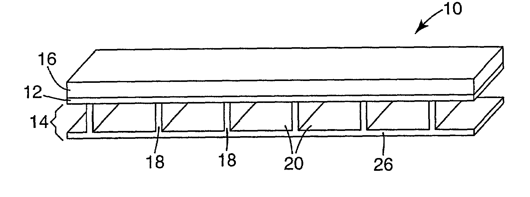
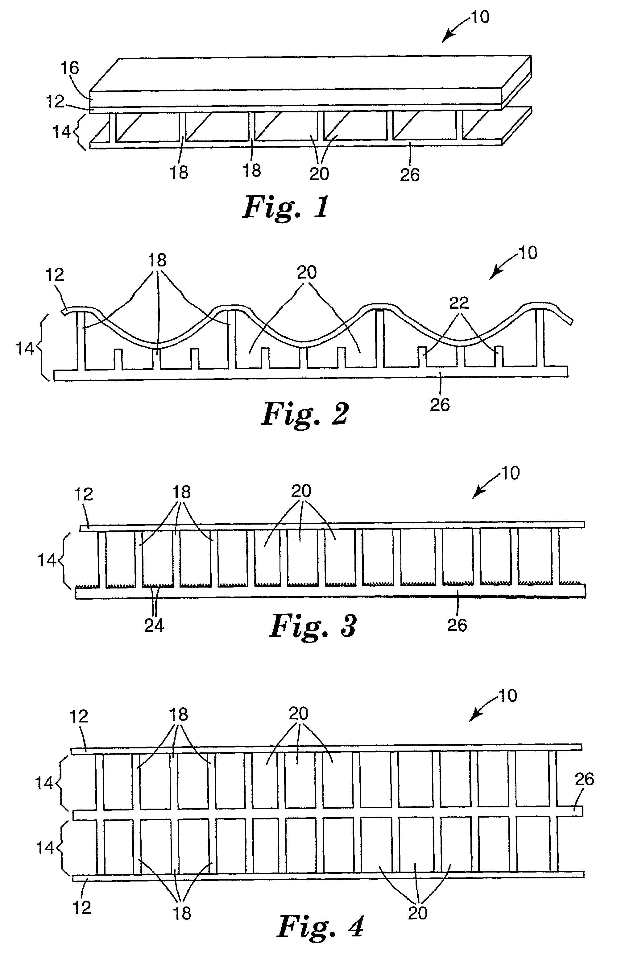
[0103]Example 1 illustrates an apparatus of the invention that was made by forming a gas delivery layer and affixing a gas permeable layer to the textured surface of the gas delivery layer.

[0104]A melt processible ethylene-polypropylene copolymer (7C55H available from Dow Chemical, Midland, Mich.) was fed into a single screw extruder (supplied by Davis Standard Corporation, Pawcatuk, Conn.) to form a gas delivery layer having one smooth surface (base layer) and one textured surface. The extruder had a diameter of 6.35 centimeters (cm) (2.5 in), a length / diameter (L / D) ratio of 24 / 1, and a temperature profile that steadily increased from approximately 177 to 232° C. (350 to 450° F.). The polymer was continuously discharged at a pressure of at least 689 kPa (100 psi) through a neck-tube heated to 232° C. (450° F.) and into a 20.32 cm (8 in.) wide MASTERFLEX™ LD-40 film die (supplied by Production Components, Eau Claire, Wis.), maintained at a temperature of 232° C. (450° F.). The die ...

example 2

[0105]Example 2 illustrates a gas delivery layer having textured features (walls) on both sides (a dual gas delivery layer).

[0106]A gas delivery film was made in a manner similar to Example 1 except the smooth surface of the gas delivery layer (surface without the walls) was melt-affixed to the smooth surface of another previously made gas delivery layer. The dual gas delivery layer that resulted is like that one shown in FIG. 4 and had a base thickness of about 355 μm (14 mils). Each wall that extended from the base had a height of 1.2 mm (46 mils), a width of 0.4 mm (16 mils) and a center-to-center spacing of 1.0 mm (40 mils).

[0107]The resulting gas delivery layer was suitable for adhering gas permeable layers to both textured surfaces (walls) by lamination techniques to make a layered sheet construction having two surfaces on which to grow biofilms.

example 3

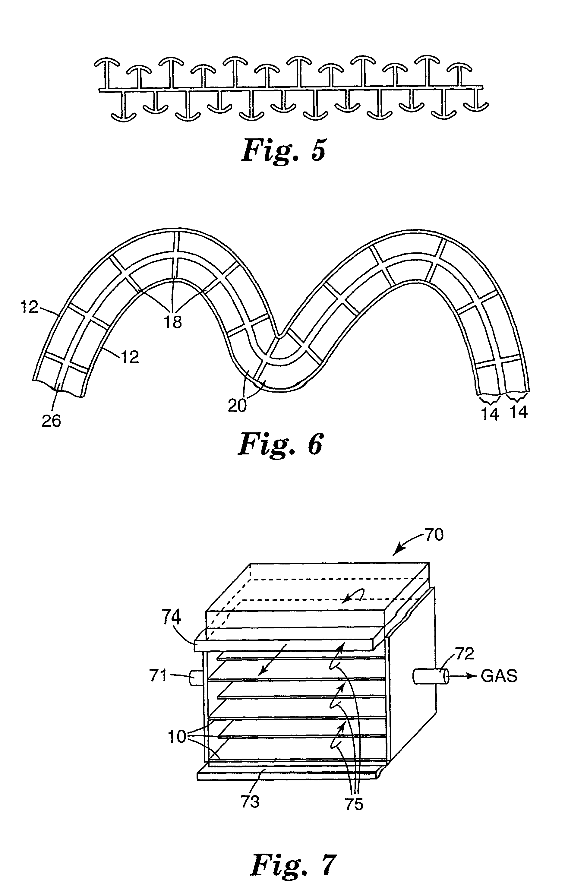
[0108]Example 3 illustrates another method of making a gas delivery layer having textured features on both sides (dual gas delivery layer).

[0109]A gas delivery layer was made in a manner similar to Example 1 except the extruder film die was configured to form walls, with hook-like protrusions, that extended about perpendicularly from both surfaces of the base layer of the gas delivery layer, as shown in FIG. 5. The dual gas delivery layer that resulted was drop-cast into a water bath to quench it. The dual gas delivery layer had a base thickness of about 254 μm (10 mils). Each wall that extended from the base had a height that alternated between 1.0 mm (40 mils) and 0.7 mm (27 mils), a width of 178 μm (7 mils) and a center-to-center spacing of 1.3 mm (50 mils). The hook-like protrusions at the end of each wall had widths of 0.7 mm (28 mils). The wall position on one surface were staggered when compared with the positions of the walls on the other surface such that one wall on the fi...


PUM

PropertyMeasurementUnit
pore sizesaaaaaaaaaa
surface energyaaaaaaaaaa

Abstract

Described is an apparatus for the removal of organic substances and/or nitrogen sources from an aqueous medium by exposing the aqueous medium to the action of microorganisms supported on a gas permeable, water impermeable layer, or on and/or in a three dimensional microbial support layer, that is proximate a gas delivery layer through which gas, preferably, oxygen-containing gas, is supplied to the gas permeable layer such that it diffuses through the gas permeable layer and is supplied to the microorganisms.

Description

FIELD OF THE INVENTION[0001]The present invention is, generally, an apparatus for substantial removal of organic substances and / or nitrogen sources from an aqueous medium containing organic substance(s) and / or nitrogen source(s). More particularly, it relates to an apparatus for the removal of organic substances and / or nitrogen sources from an aqueous medium by exposing the contaminated aqueous medium to the action of microorganisms supported on a water impermeable, gas permeable layer that is laminated to a gas delivery layer through which gas is supplied to the gas permeable layer such that it permeates the gas permeable layer and is supplied to the microorganisms on the gas permeable layer.BACKGROUND OF THE INVENTION[0002]Water treatment processes commonly utilize microbes, mainly bacteria, to produce enzymes that catalyze the degradation of unwanted, typically organic, material in water, this material being used as a fuel source by the microbes. Some standard processes for biolo...

Claims


Application Information

Patent Timeline
Patent Type & Authority Patents(United States)
IPC IPC(8): B01D29/07B01D53/22B01D71/32B01D71/70B32B3/24B32B3/26B32B5/18C02F3/06C02F3/10C02F3/20C02F3/34
CPCB32B3/26B32B5/18C02F3/102C02F3/201C02F3/108Y10T428/24694Y02E50/343Y10T428/249981Y10T428/249992Y10T428/249991Y10T428/249953Y02E50/30Y02W10/10C02F3/10C02F3/20
Inventor HESTER, JONATHAN F.SPIEWAK, BRIAN E.HOLM, DAVID R.HALL, JR., JERALD W.KIRK, SETH M.DAVID, MOSES M.LAKSHMI, BRINDA B.
Owner 3M INNOVATIVE PROPERTIES CO
Why Eureka
Try Eureka