
Yaw control for an automotive vehicle using steering actuators

a technology of steering actuators and actuators, which is applied in the direction of steering initiation, instruments, vessel construction, etc., can solve the problems that the above mentioned yaw control systems do not control the lateral or yaw response, and achieve the effects of safe response, easy implementation, and great flexibility in controlling

Inactive Publication Date: 2006-12-05
FORD GLOBAL TECH LLC
View PDF35 Cites 30 Cited by
  • Summary
  • Abstract
  • Description
  • Claims
  • Application Information

AI Technical Summary

Benefits of technology

[0008]One advantage of the invention is that such systems may be easily implemented into a steer-by-wire system. Another advantage of the invention is that great flexibility in controlling the vehicle lateral dynamic response independent of the steady state response is achieved. For example, a defined transient yaw response independent of the steady state yaw gain of the uncontrolled vehicle may be achieved. For example, the defined transient yaw response can be controlled such that it has critical yaw damping while the steady state gain is that of an under-steered vehicle (which is under-damped). The vehicle yaw gain thus reaches a maximum value at the characteristic speed then decreases as the speed increases further. This is generally considered a safer response. Also, the ability to increase the perceived linear range of the vehicle lateral response by independently changing the steering wheel to road wheel steer angle ratio. For example, road wheel angle / steering wheel gain can increase as lateral acceleration increases (in a closed-loop control) to extend the perceived line or range response of the vehicle. The vehicle yaw response increases as driver steering input increases for a given speed to provide improved vehicle response using closed-loop control. This can be tailored in software according to the desired vehicle driving / handling characteristics.

Problems solved by technology

The yaw control systems mentioned above thus do not control the lateral or yaw response by controlling steering of the front wheels directly.

Method used


Image

  • Yaw control for an automotive vehicle using steering actuators
  • Yaw control for an automotive vehicle using steering actuators
  • Yaw control for an automotive vehicle using steering actuators

Examples


Embodiment Construction

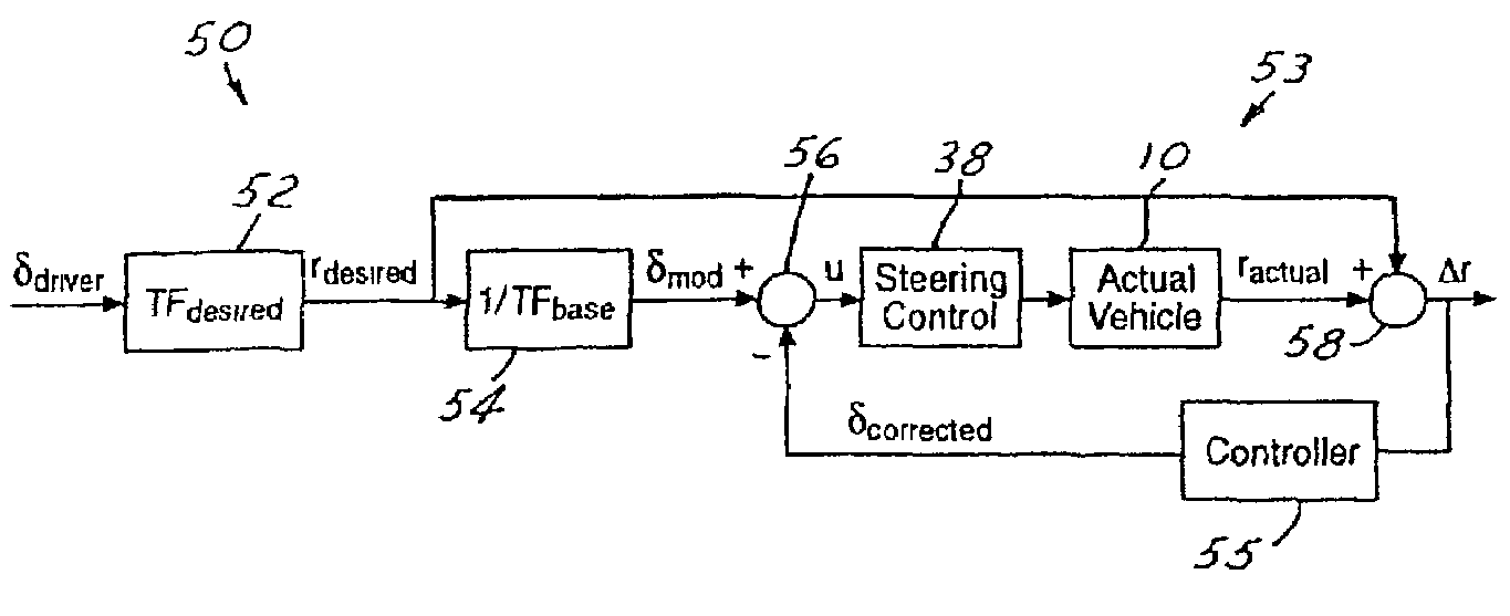
[0014]A method according to the present invention is intended for use with yaw control systems implemented with electronically controlled or electrically actuated steering systems in automotive vehicles. However, the invention could easily be adapted for use in yaw control systems on other motor vehicles, such as watercraft and aircraft as well as on other vehicle systems, such as active tilt, rollover control or active suspension. While the example set forth herein is described with respect to a yaw rate signal, various lateral dynamic conditions may be used such as side slip angle, lateral acceleration and curvature response gain.

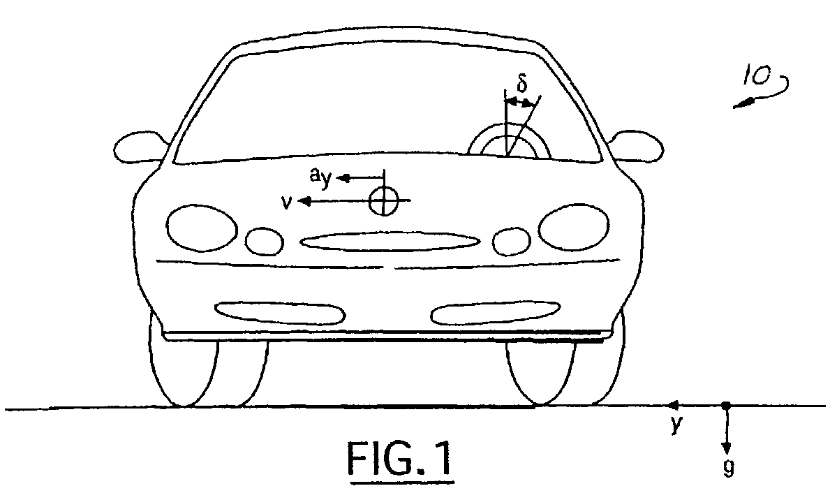
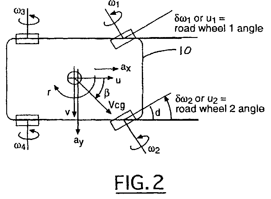
[0015]Referring now to FIGS. 1 and 2, various operating parameters and variables used by the present invention are illustrated as they relate to the application of the present invention to a ground based motor vehicle 10. Those skilled in the art will immediately recognize the basic physics represented by these illustrations, thereby make the adaptation t...


PUM


Abstract

A stability control system (24) for an automotive vehicle includes a plurality of sensors sensing the dynamic conditions of the vehicle. The sensors include a steering angle sensor (35) and a yaw rate sensor (28). The controller (26) is coupled to the steering angle sensor (35) and the yaw rate sensor (28). The controller (26) determines a desired yaw rate in response to the steering wheel angle input, determines a corrected steering wheel input as a function of the desired yaw rate of an ideal vehicle and the vehicle yaw rate, and controls the road wheel steer angle (front, rear, or both) steering actuator in response to the corrected steering wheel input, the yaw rate and the modified steering wheel input, vehicle speed, lateral acceleration, longitudinal acceleration, yaw rate, steering wheel angle, and road wheel angles.

Description

BACKGROUND OF INVENTION[0001]The present invention relates generally to a dynamic behavior control apparatus for an automotive vehicle, and more specifically, to a method and apparatus for controlling the lateral dynamics of the vehicle by controlling the front and / or rear wheel steer angle for the vehicle.[0002]Dynamic control systems for automotive vehicles have recently begun to be offered on various products. Antilock braking systems (ABS) and traction control (TC) control tire slip ratios. More advanced dynamic control systems typically control the side slip angle and yaw response of the vehicle by controlling the tractive forces and / or braking torque at the various wheels of the vehicle. Side slip and yaw control systems typically compare the desired direction, yaw response, and lateral acceleration of the vehicle based upon the steering wheel angle, speed, and the direction of travel to an ideal (stable) vehicle model. By regulating the amount of braking torque and tractive f...

Claims


Application Information

Patent Timeline
IPC IPC(8): B62D5/04B60T8/1755B60W30/02B60W50/00B62D6/00B62D7/15
CPCB60T8/1755B60W30/02B62D6/003B62D7/159B60T2260/02B60W2050/0008B60W2050/0012B60W2050/0013B60W2050/0028B60W2510/20B60W2520/10B60W2520/105B60W2520/125B60W2520/14B60W2520/16B60W2520/28B60W2710/18B60W2710/207B60W2720/14B60W2540/18
Inventor MATTSON, KEITH GLENNRHODE, DOUGLAS SCOTTBROWN, TODD ALLEN
Owner FORD GLOBAL TECH LLC
Learn More