Method of making capacitor element used for solid electrolytic capacitor

Inactive Publication Date: 2006-12-05
ROHM CO LTD
View PDF6 Cites 9 Cited by
  • Summary
  • Abstract
  • Description
  • Claims
  • Application Information

AI Technical Summary

Benefits of technology

[0011]The present invention has been proposed under the circumstances described above. It is, therefore, an object of the present invention to provide a capacitor element fabrication method which can overcome the above problem.

Problems solved by technology

Therefore, when heated (this may happen when the capacitor is soldered to a printed circuit board, for example), the electrolyte layer and the graphite layer tend to expand at different rates, thereby causing delamination therebetween.
Unfavorably, this leads to the deterioration of the impedance characteristics of the capacitor device.
The inventor of the present application conducted experiments and found that there is a drawback in the prior art method.
With such a high mixing rate, however, the resultant electrolyte layer tends to have a considerably rough surface to an extent that the irregularity cannot be satisfactorily smoothed out merely by overlapping the upper layers (i.e., the graphite layer and the metal layer).

Method used


Image

  • Method of making capacitor element used for solid electrolytic capacitor
  • Method of making capacitor element used for solid electrolytic capacitor
  • Method of making capacitor element used for solid electrolytic capacitor

Examples


second embodiment

[0045]Reference is now made to FIGS. 13–18 illustrating the present invention.

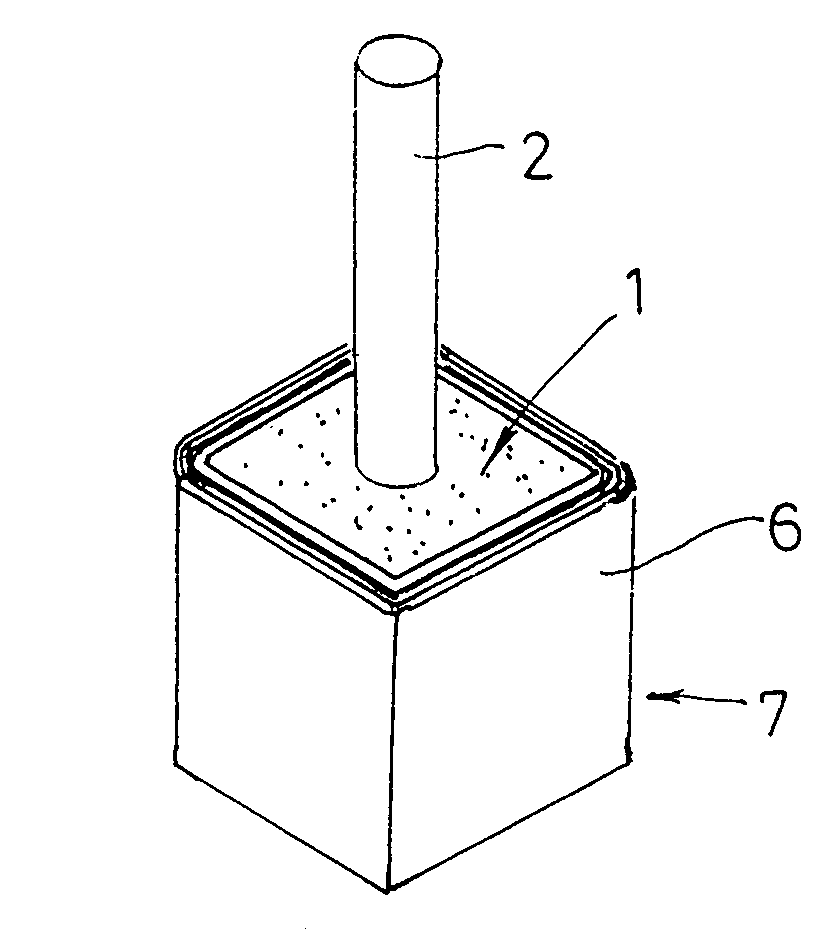
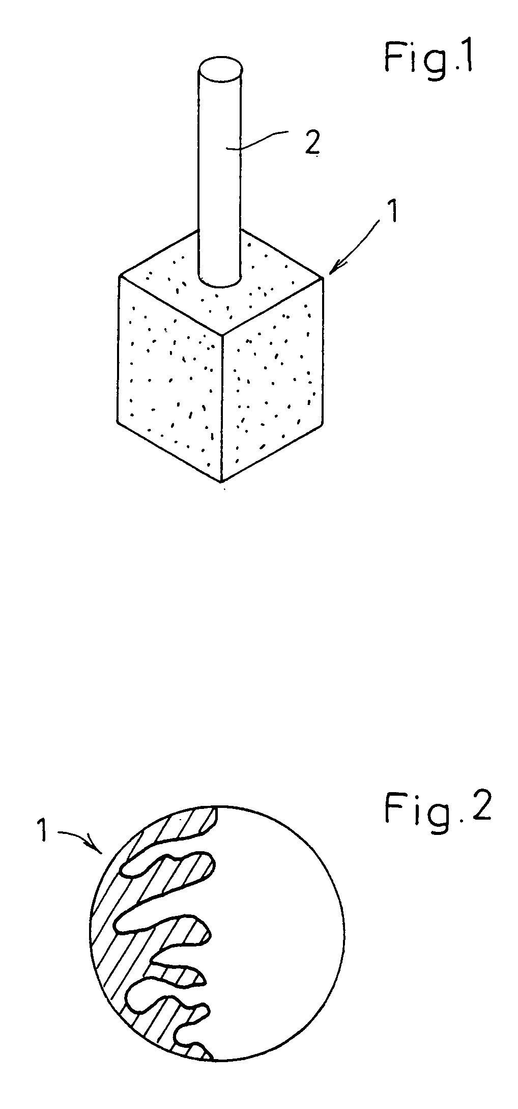
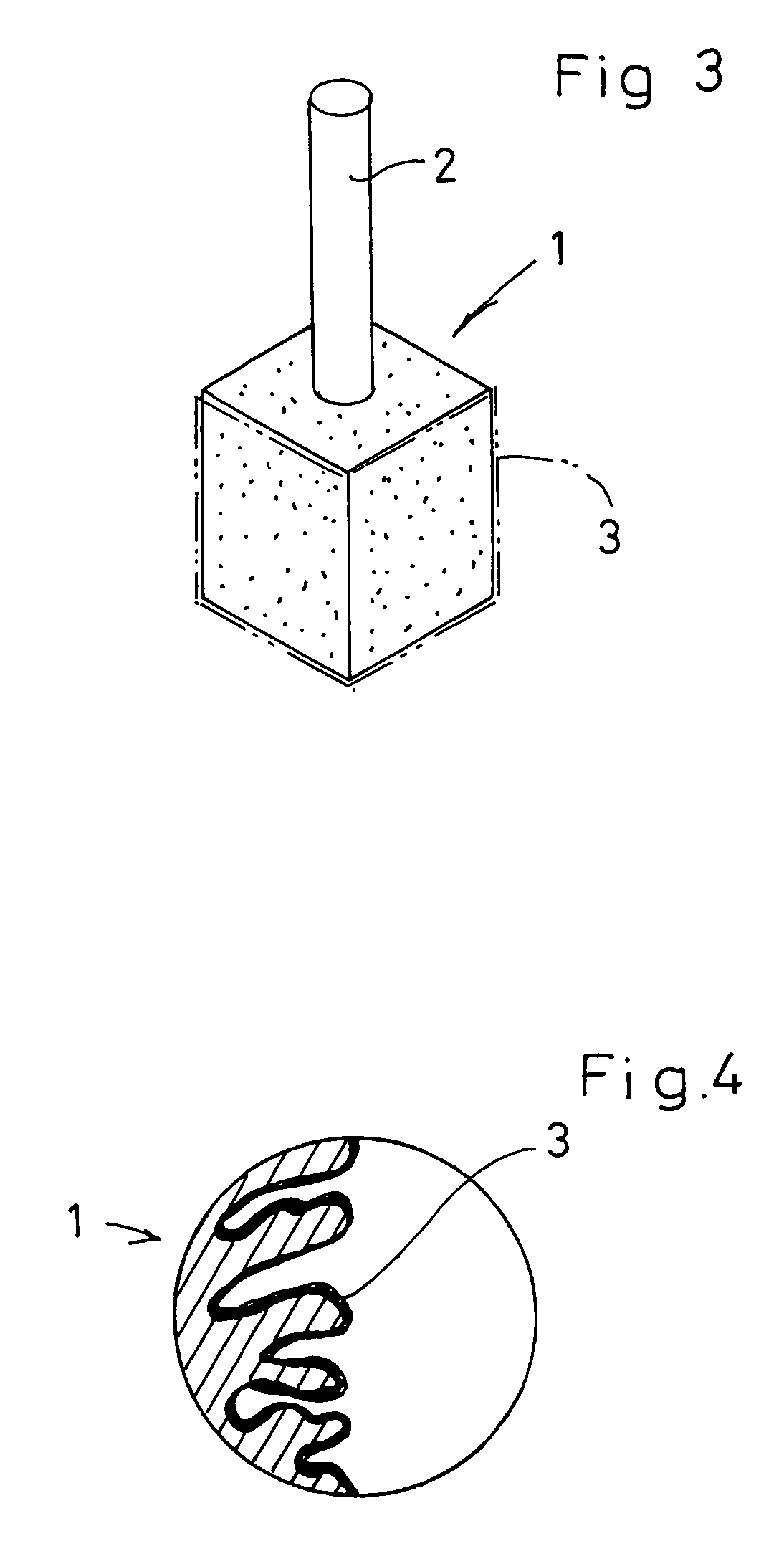
[0046]The anode chip fabrication method of the second embodiment is basically the same as that of the first embodiment, except for the step of forming an intermediate layer between the electrolyte layer 4 and the graphite layer 5. Specifically, first, a compacted anode chip 1 as the one shown in FIG. 1 is prepared, and then a dielectric layer 3 (see FIG. 3) and a first solid electrolyte layer 4 (see FIG. 5) are formed on the chip 1 in the same manner as in the first embodiment. Thereafter, an intermediate layer 5′ is formed on the electrolyte layer 4 by application of a graphite solution containing manganese dioxide powder. Specifically, the anode chip 1, with the electrolyte layer 4 formed, is immersed in the MnO2-containing graphite solution and then taken out of the solution for drying at 150–200° C. This immersion-drying process is performed at least once, preferably two or three times. As a result, th...


PUM

PropertyMeasurementUnit
Temperatureaaaaaaaaaa

Abstract

A method of making a capacitor element used for a solid electrolyte capacitor is provided. The method includes steps of forming a dielectric layer, a solid electrolyte layer of manganese dioxide, a graphite layer and a metal layer in this order on an anode chip of valve metal. The method further includes a step of forming an intermediate layer between the electrolyte layer and the graphite layer. The intermediate layer is made by application of manganese nitrate solution containing 0.5–2.0 wt % of graphite powder or by application of a graphite material containing manganese dioxide powder.

Description

BACKGROUND OF THE INVENTION[0001]1. Field of the Invention[0002]The present invention relates to a method of making a capacitor element to be incorporated in a solid electrolytic capacitor which is produced with the use of a valve metal such as tantalum or niobium.[0003]2. Description of the Related Art[0004]A conventional capacitor element of the above-mentioned type is made in the following manner, for example.[0005]First, powder of a valve metal, e.g., tantalum, is compressed and baked to produce an anode chip. Then, the anode chip is dipped into a chemical solution (e.g. an aqueous solution of phosphoric acid) for anodic oxidation. Thus, a highly insulating dielectric layer of tantalum pentoxide (Ta2O5) is formed on the metal particles of the anode chip. Then, a solid electrolyte layer of manganese dioxide (MnO2) is formed on the Ta2O5-dielectric layer by dipping the anode chip into an aqueous solution of manganese nitrate and then baking the chip at 200–250° C. after taken out ...

Claims


Application Information

Patent Timeline
IPC IPC(8): H01G9/00H01G9/032H01G9/04H01G9/042H01G9/15
CPCH01G9/0425Y10T29/417
Inventor NAKAMURA, TAKAHIRO
Owner ROHM CO LTD
Why Eureka
Try Eureka