Resilient probes for electrical testing

a technology of resistive probes and probe cards, which is applied in the direction of electrical testing, measurement devices, instruments, etc., can solve the problems of high cost of probe cards, sensitive handling, and excessive labor of assembly of probe cards, and achieve the effect of simplifying the subsequent processing steps of semiconductor devices and inexpensive test cards

Active Publication Date: 2006-12-05
TEXAS INSTR INC
View PDF4 Cites 13 Cited by
  • Summary
  • Abstract
  • Description
  • Claims
  • Application Information

AI Technical Summary

Benefits of technology

[0015]It is another technical advantage of the invention that the test card manufacture is inexpensive compared to cards made by the conventional technology; it uses automated processes such as ball formation in wire bonders, and automated assembly. Another technical advantage of the invention is the fact that the testing procedure leaves only minimal marks in the metallization of the test pads, which greatly simplifies subsequent processing steps of the semiconductor devices.

Problems solved by technology

Since there are commonly several hundred of these needles per probe card, and the needle pitch at the tips is of the order of 40 to 70 μm, the assembly of the probe cards is exceedingly tedious.
Consequently, probe cards are very expensive, and their handling is very sensitive.
It is well known in the semiconductor industry, how frustrating it is when one or more needle is misshaped or does no longer operate reliably.
Given the large number of needles, their dense packing, and their mechanical sensitivity, malfunctioning is unfortunately experienced frequently after only several hundred touch-downs so that expensive probe cards need to be replaced.

Method used


Image

  • Resilient probes for electrical testing
  • Resilient probes for electrical testing
  • Resilient probes for electrical testing

Examples


Embodiment Construction

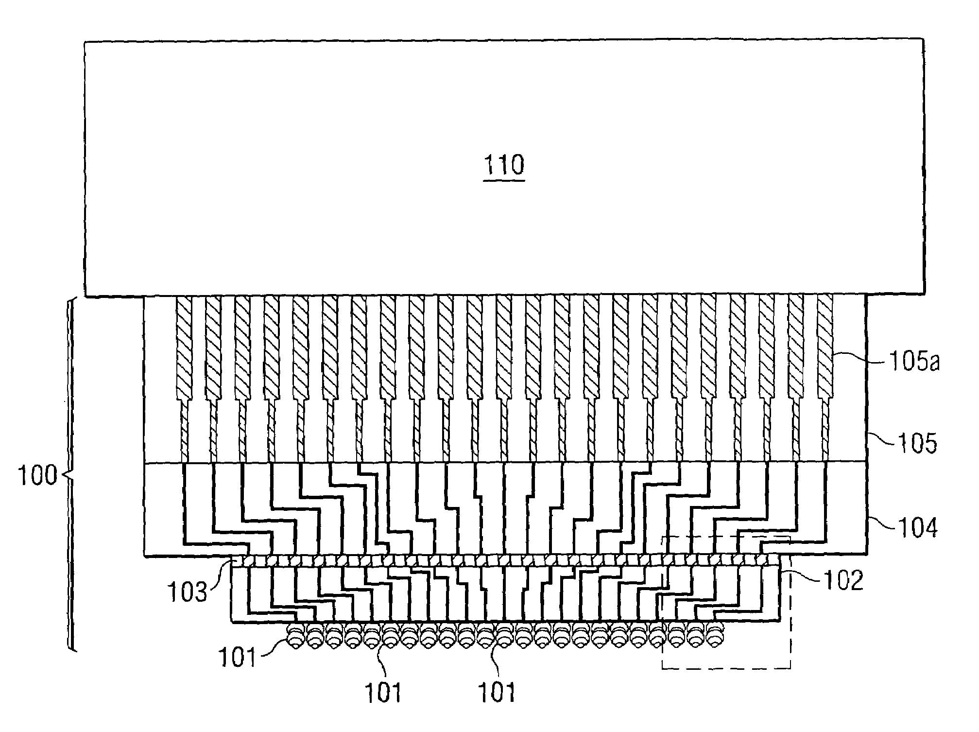
[0025]FIG. 1 shows schematically a cross section through an apparatus for testing according to the invention. The apparatus is generally designated 100, and the test equipment 110. Usually, the apparatus is electrically and mechanically connected to the test equipment by a plurality of pins (not shown on FIG. 1) which are pushed into the corresponding sockets of the equipment.

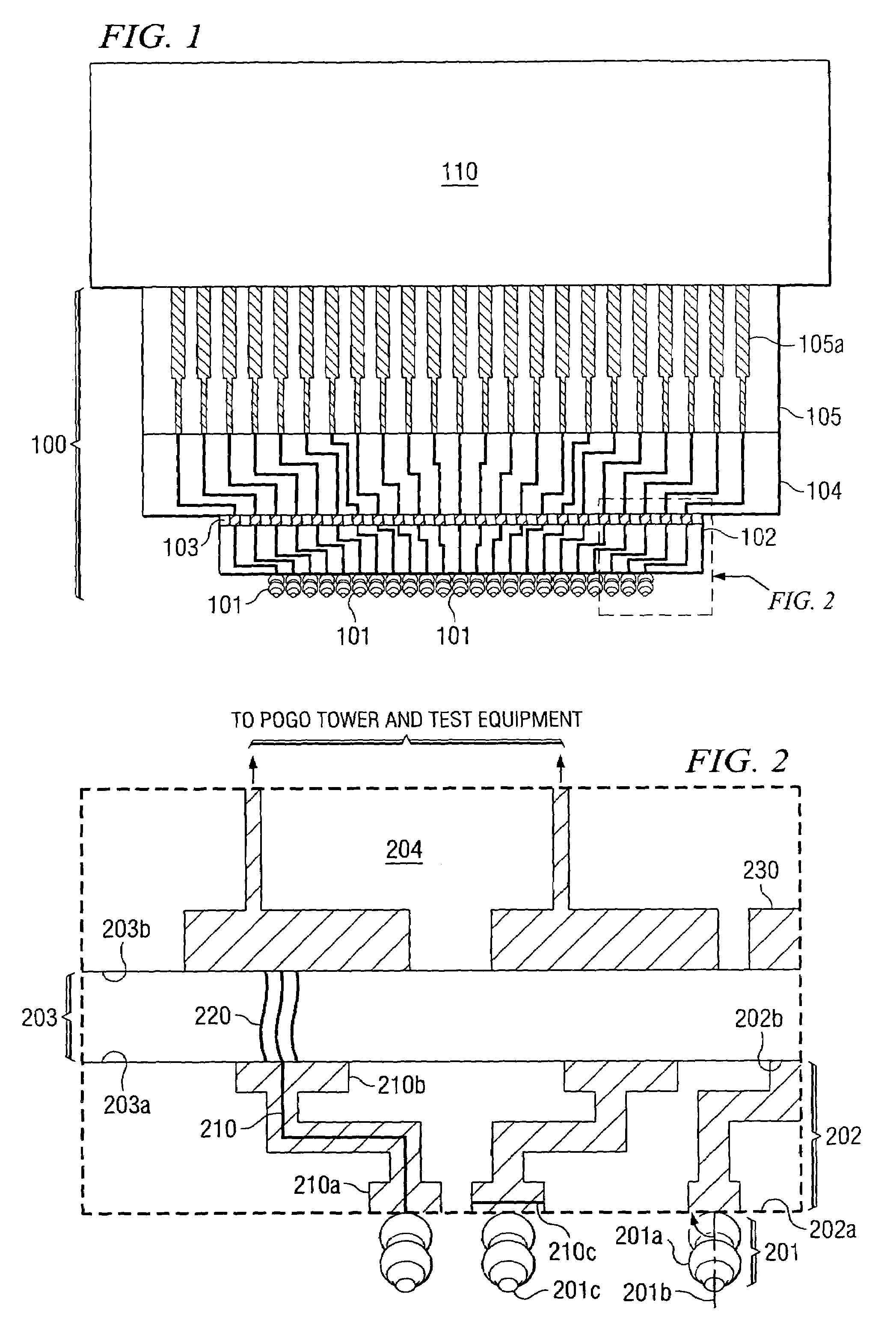
[0026]The apparatus 100 consists of several portions: At the surface facing the device-to-be-probed are the actual probes 101, which establish the electrical contacts to the device test pads. The composition, orientation and distribution of probes 101 are discussed in more detail in FIGS. 2 thru 8. Probes 101 are attached the insulating holder 102, which is traversed by metal-filled vias and described in more detail in FIGS. 2 and 7. Holder 102 in turn is attached to a sheet 103 of resilient insulating material, which is traversed by conductive traces and discussed in more detail in FIGS. 2 and 7. Resilient she...


PUM


Abstract

An apparatus for electrical testing having probes (201) constructed of metal elements (201a) of about equal size bonded together in substantially linear sequence. Further an insulating holder (202) having first and second surfaces and a plurality of metal-filled vias (210) traversing the holder from the first to the second surface; the vias form contact pads on the first and second surfaces. The contact pads (210a) of the first holder surface have a probe attached so that the probe is positioned about normal to the surface. A sheet (203) of resilient insulating material, which has first and second surfaces and a thickness traversed by a plurality of conducting traces (220), has its first sheet surface attached to the second holder surface so that at least one of the traces contacts one of the contact pads, respectively, to provide an electrical path to the second sheet surface. A printed circuit board, suitable for insertion into an electrical test apparatus, is attached to the second sheet surface so that a continuous electrical path is established from the apparatus to each of the probes.

Description

[0001]This application claims priority under 35 USC § 119 (e) (1) of provisional application Ser. No. 60 / 665,676 filed Mar. 28, 2005.FIELD OF THE INVENTION[0002]The present invention is related in general to the field of semiconductor devices and testing and more specifically to the structure of a test head and the corresponding testing method, which provide testing of devices and is particularly suitable for fine pitch or even irregular distribution of signal and power pads.DESCRIPTION OF THE RELATED ART[0003]Semiconductor devices and especially integrated circuits are subjected twice to significant testing. The final test is a functional a.c. test to check the performance of the fully assembled and encapsulated device before its delivery to the customer. Among the parameters tested are speed, propagation delay, and signal rise and fall. The final test needs to ascertain that the device meets the customer's specification and is, consequently, often coupled with an accelerated life ...

Claims


Application Information

Patent Timeline
Patent Type & Authority Patents(United States)
IPC IPC(8): G01R31/02
CPCG01R1/07378G01R1/06738G01R1/06744G01R1/07321G01R3/00
Inventor STILLMAN, DANIEL J.
Owner TEXAS INSTR INC
Why Eureka
Try Eureka