Catoptric imaging systems comprising pellicle and/or aperture-array beam-splitters and non-adaptive and/or adaptive catoptric surfaces

a catoptric imaging and aperture array technology, applied in the field of interferometric imaging and metrology systems, can solve the problems of increasing the signal-to-noise ratio, introducing the possibility of non-common path phase errors, and concomitant increase in the throughput of a metrology tool using the catoptric imaging system, so as to reduce the magnitude of background contribution and increase the resolution of the imaging system

Inactive Publication Date: 2006-12-05
ZETETIC INST
View PDF67 Cites 6 Cited by
  • Summary
  • Abstract
  • Description
  • Claims
  • Application Information

AI Technical Summary

Benefits of technology

[0019]Catoptric IR to EUV imaging systems configured with large numerical apertures are described that reduce the effects of off-axis optical aberrations for generation of enhanced fields of view. The catoptric IR to EUV imaging systems comprise a thin beam-splitter, thin with respect to generation of optical aberrations and / or internal absorption, and / or an aperture-array beam-splitter. The effects of off-axis aberrations are reduced in certain embodiments by complimentary arrays of orthogonal slits located on the sagittal and tangential surfaces in either the object space and / or in the image space of the catoptric imaging systems. The catoptric imaging systems in the certain embodiments may be used to generate a diffraction limited spot on a measurement object or used to obtain diffraction limited information about a spot on a measurement object. The catoptric surfaces of the catoptric imaging systems may comprise adaptive catoptric surfaces wherein each of the one or more adaptive catoptric surfaces is generated by an array of reflecting elements. The thin beam-splitter may be a pellicle beam-splitter comprising a self supporting stack of one or more thin layers of refractive media and the aperture-array beam-splitter may comprise a thin self supporting reflective stack of one or more refractive layers with an array of transmitting apertures or an array or grid of conducting wires wherein the size of the apertures is generally larger than the wavelength of an optical beam being focused by the imaging systems.
[0020]In comparison to certain catoptric imaging systems that comprise a non-thin beam-splitter, the use of a thin beam-splitter reduces the magnitude of both off-axis and on-axis aberrations and further reduces the optical path length of measurement and / or reference beams in a dispersive or refractive medium which is particularly important when working in the UV to EUV. The catoptric imaging systems may be configured to have a large working distance, e.g., 6 mm. In addition, the catoptric imaging systems may be employed in interferometric or non-interferometric imaging systems operating in a reflecting mode to measure properties of fields reflected / scattered by a measurement object or substrate or in a transmission mode to measure properties of fields transmitted / scattered by a measurement object or substrate, e.g., a reticle mask.
[0021]The positions and orientations of the reflecting elements of the one or more adaptive surfaces are controlled by transducers and a servo control system. The use of multi-element adaptive catoptric surfaces makes it possible to relax tolerances on the surface figures and locations of surfaces of the reflecting elements, makes it possible to introduce a mode of operation such that the image of a plane section of a measurement object is fixed in an image plane for a short period of time that covers the duration of a beam pulse generating the image although the plane section of the measurement object is moving in the object space at a high slew rate, makes it possible to introduce modes of operation that increases the speed at which lateral and vertical scans of a substrate may be implemented, makes it possible to introduce modes of operation that increase the signal-to-noise ratios for image information generated with the catoptric imaging systems, and makes it possible to operate in either a differential or non-differential interferometric mode with the option of switching rapidly between either of the differential or the non-differential modes of operation.

Problems solved by technology

The increase in intensity of desired images and the reduction of statistical errors lead to an increase in signal-to-noise ratios and to a concomitant increase in throughput of a metrology tool using the catoptric imaging system.
In the case where a beam-splitter is used for the beam combining function, the measurement beam component and the reference beam component of the combined beam may have subsequent to the beam-splitter different paths in the optical elements which introduce the possibility of non-common path phase errors.

Method used


Image

  • Catoptric imaging systems comprising pellicle and/or aperture-array beam-splitters and non-adaptive and/or adaptive catoptric surfaces
  • Catoptric imaging systems comprising pellicle and/or aperture-array beam-splitters and non-adaptive and/or adaptive catoptric surfaces
  • Catoptric imaging systems comprising pellicle and/or aperture-array beam-splitters and non-adaptive and/or adaptive catoptric surfaces

Examples


Embodiment Construction

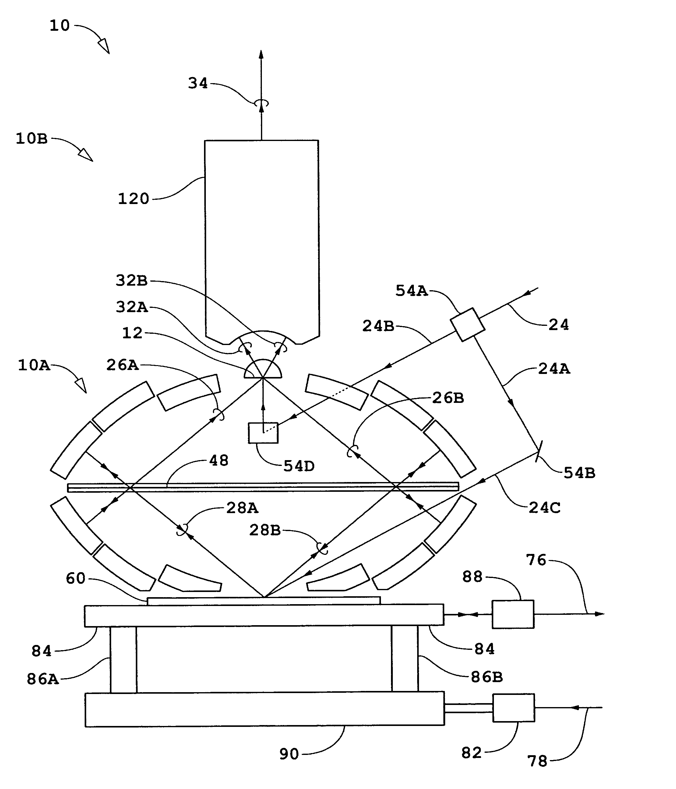
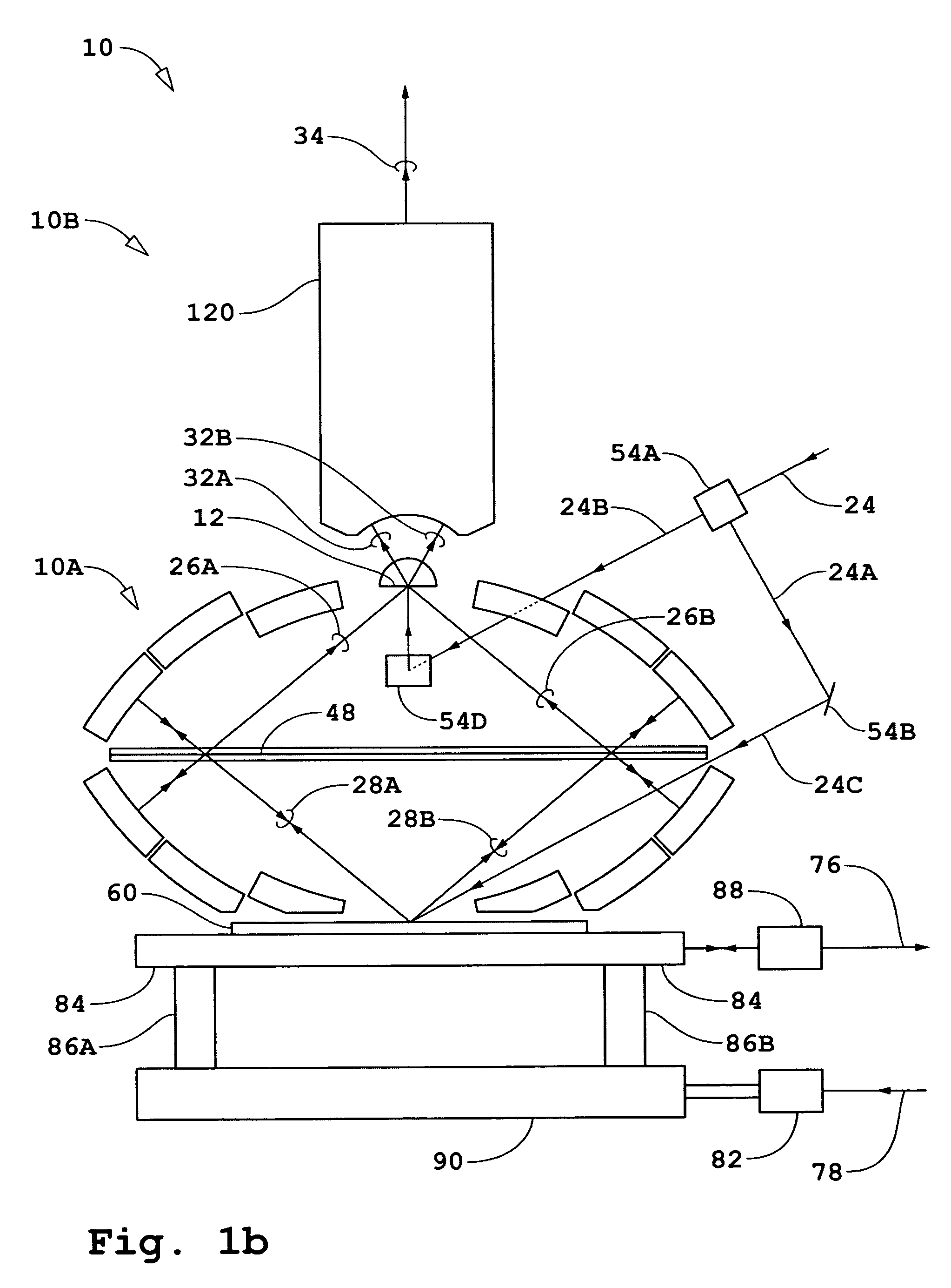
[0072]A general description of embodiments incorporating the present invention will first be given for interferometer systems wherein either a N-dimensional bi- or quad-homodyne detection method is used where N is an integer. Referring to FIG. 1a, an interferometer system is shown diagrammatically comprising an interferometer 10, a source 18, a beam-conditioner 22, a detector 70, an electronic processor and controller 80, and a measurement object shown as substrate 60. Source 18 generates input beam 20. The interferometer system shown in FIG. 1a is for the case of an imaging system operating in a reflecting mode to measure properties of fields reflected / scattered by substrate 60. For the case of operation in a transmission mode, a portion of beam 24 split off as a measurement beam is incident on substrate 60 from the backside of substrate 60 such as shown diagrammatically in FIG. 2a. Source 18 is preferably a pulsed source that generates beam 20 with a single frequency component. Be...


PUM


Abstract

An interferometry system including: a first imaging system that directs a measurement beam at an object to produce a return measurement beam from the object, that directs the return measurement beam onto an image plane, and that delivers a reference beam to the image plane; and a beam combining element in the image plane, said beam combining element comprising a first layer containing an array of sagittal slits and a second layer containing an array of tangential slits, wherein each slit of the array of sagittal slits is aligned with a corresponding different slit of the array of tangential slits, wherein the beam combining element combines the return measurement beam with the reference beam to produce an array of interference beams.

Description

[0001]This application also claims the benefit of U.S. Provisional Application No. 60 / 611,564, filed Sep. 20, 2004, incorporated herein by reference.TECHNICAL FIELD[0002]This invention relates to interferometric imaging and metrology systems operating in the IR to EUV such as used in fabrication and inspection of wafers, integrated circuits, and reticle masks.RELATED APPLICATIONS[0003]The following applications are related to the present application: U.S. Pat. No. 6,552,852, issued Apr. 22, 2003 and entitled “Catoptric and Catadioptric Imaging Systems,” (ZI-38); U.S. Ser. No. 60 / 447,254, filed Feb. 13, 2003, and U.S. Ser. No. 10 / 778,371, filed Feb. 13, 2004, both of which are entitled “Transverse Differential Interferometric Confocal Microscopy,” (ZI-40); U.S. Ser. No. 60 / 448,360, filed Feb. 19, 2003, and U.S. Ser. No. 10 / 782,057, filed Feb. 19, 2004, both of which are entitled “Longitudinal Differential Interferometric Confocal Microscopy For Surface Profiling,” (ZI-41); U.S. Ser. ...

Claims


Application Information

Patent Timeline
Patent Type & Authority Patents(United States)
IPC IPC(8): G01B9/02
CPCG01J1/58G01N21/45G01N21/9501G01B9/02028G01B9/02056G01B9/02022G01J3/04G01J3/2823
Inventor HILL, HENRY ALLEN
Owner ZETETIC INST
Why Eureka
Try Eureka