Exhaust gas cleaning system having particulate filter

a technology of exhaust gas cleaning and filter, which is applied in the direction of mechanical equipment, machines/engines, electric control, etc., can solve the problems of engine efficiency decline, pressure loss increase, and major reduction of particulate discharge from diesel engines, so as to reduce the dpf and reduce the effect of fuel consumption

Inactive Publication Date: 2006-12-12
DENSO CORP
View PDF7 Cites 38 Cited by
  • Summary
  • Abstract
  • Description
  • Claims
  • Application Information

AI Technical Summary

Benefits of technology

[0009]It is therefore an object of the present invention to provide an exhaust gas cleaning system having a diesel particulate filter (DPF), which is capable of efficiently regenerating the DPF while inhibiting increase in fuel consumption with relatively simple control.
[0012]Thus, the regenerating efficiency is improved, since the regeneration performing means operates the regenerating means only when the operating state of the engine is determined to be in the suitable area, in the case where the collecting state parameter is equal to or greater than the first threshold and is less than the second threshold. Moreover, the safety is improved since the regeneration performing means operates the regenerating means when the collecting state parameter is equal to or greater than the second threshold, regardless of the result of the determination performed by the regeneration suitability determining means. Thus, the regeneration is performed safely and efficiently and the deterioration of the fuel consumption is inhibited with the relatively simple control, improving the practicability.

Problems solved by technology

Lately, reduction of particulate matters discharged from a diesel engine has been a major issue as an environmental measure.
If the collected particulate matters keep on depositing in the DPF, a pressure loss may increase and engine efficiency may decrease.
However, if the DPF is regenerated frequently by the above regenerating methods, fuel consumption is increased because energy is consumed to increase the temperature of the exhaust gas.
As a result, control of the regeneration is complicated.

Method used


Image

  • Exhaust gas cleaning system having particulate filter
  • Exhaust gas cleaning system having particulate filter
  • Exhaust gas cleaning system having particulate filter

Examples


first embodiment

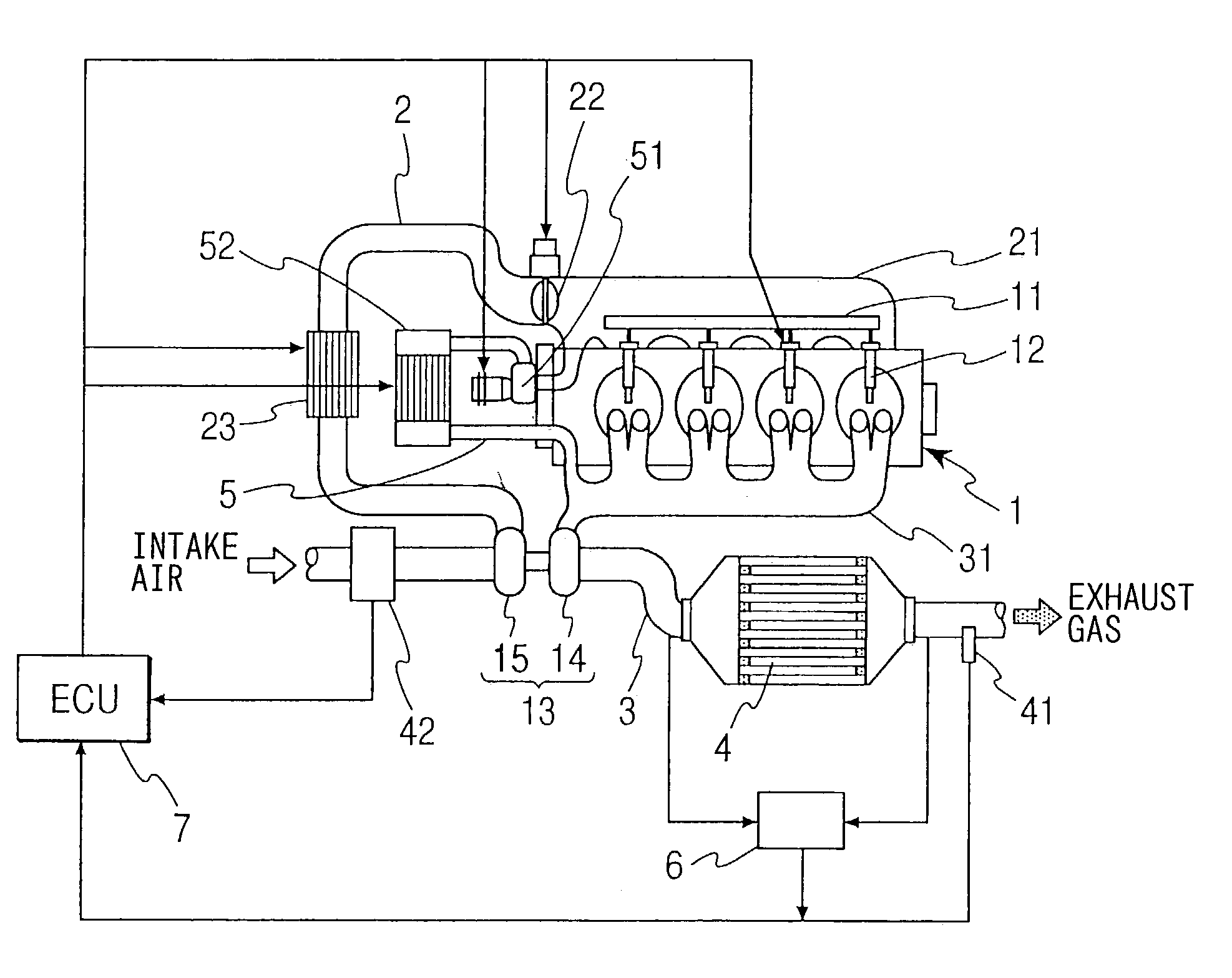
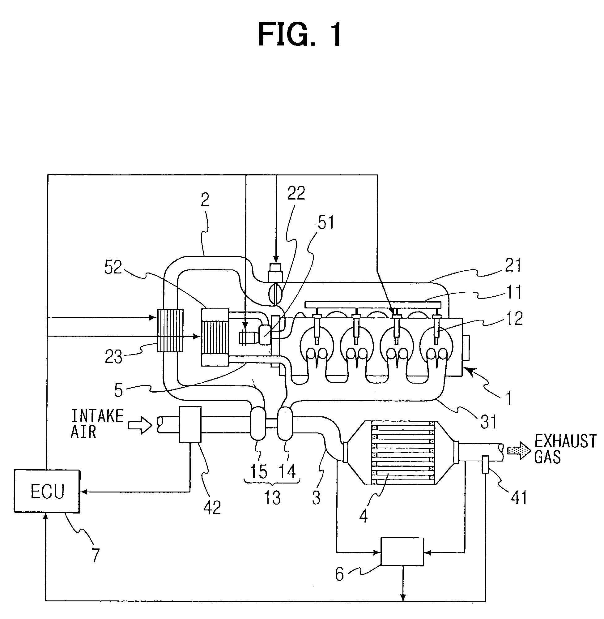
[0024]Referring to FIG. 1, a diesel engine 1 having an exhaust gas cleaning system of the first embodiment is illustrated. The diesel engine 1 has a common rail 11, which is common to respective cylinders, and a plurality of fuel injection valves 12, which are connected to the common rail 11 and inject fuel into combustion chambers of the respective cylinders. An intake manifold 21 of the engine 1 is connected with an intake pipe 2. An intake throttle 22 is disposed in the connection between the intake manifold 21 and the intake pipe 2 for regulating a flow rate of intake air.

[0025]An exhaust manifold 31 of the engine 1 is connected with an exhaust pipe 3. A diesel particulate filter (DPF) 4 is disposed in the exhaust pipe 3. The DPF 4 has a publicly known structure. The DPF 4 is made of heat-resistant ceramics such as cordierite and is formed in the shape of a honeycomb. The honeycomb has a matrix of porous filter walls forming a multiplicity of cells extending from one end to anot...

second embodiment

[0041]Next, regeneration control performed by an ECU 7 of a diesel engine 1 according to the second embodiment will be explained based on a flowchart shown in FIG. 5. In the second embodiment, the temperature increase of the DPF 4 is not performed when the operating state of the engine 1 is in a temperature increase dispensable area where the particulate matters can combust spontaneously even if the regenerating means is not operated. First, in Step S201, the ECU 7 calculates the PM collection quantity M based on the exhaust gas flow rate (volume flow rate) and the pressure difference between the upstream portion and the downstream portion of the DPF 4 like the first embodiment. Then, in Step S202, it is determined whether the calculated PM collection quantity M is “equal to or greater than” the first threshold A1 or not. If the result of the determination in Step S202 is “NO”, the processing returns to the start.

[0042]If the result of the determination in Step S202 is “YES”, the pr...

third embodiment

[0046]Next, regeneration control performed by an ECU 7 of a diesel engine 1 according to the third embodiment will be explained based on a flowchart shown in FIG. 6. In the third embodiment, the temperature increase of the DPF 4 is not performed when the operating state of the engine 1 is in a particulate matter combustion impossible area where the temperature increase of the DPF 4 is difficult. First, in Step S301, the ECU 7 calculates the PM collection quantity M based on the exhaust gas flow rate (volume flow rate) and the pressure difference between the upstream portion and the downstream portion of the DPF 4 like the first embodiment. Then, in Step S302, it is determined whether the calculated PM collection quantity M is “equal to or greater than” the first threshold A1 or not. If the result of the determination in Step S302 is “NO”, the processing returns to the start.

[0047]If the result of the determination in Step S302 is “YES”, the processing proceeds to Step S303. In Step ...


PUM


Abstract

An exhaust gas cleaning system for a diesel engine has a diesel particulate filter (DPF) disposed in an exhaust pipe. An electronic control unit of the system controls regeneration of the DPF. The DPF is heated and regenerated only when an operating state of the engine is in an area where temperature-increasing efficiency is high, in the case where a quantity of particulate matters collected by the DPF is equal to or greater than a first threshold and is less than a second threshold. The second threshold is greater than the first threshold. If the quantity of the collected particulate matters becomes equal to or greater than the second threshold, the regeneration is performed even if the operating state is not in the area of the high temperature-increasing efficiency.

Description

CROSS REFERENCE TO RELATED APPLICATION[0001]This application is based on and incorporates herein by reference Japanese Patent Application No. 2002-173017 filed on Jun. 13, 2002.BACKGROUND OF THE INVENTION[0002]1. Field of the Invention[0003]The present invention relates to an exhaust gas cleaning system having a particulate filter for collecting particulate matters included in exhaust gas of an internal combustion engine. Specifically, the present invention relates to an exhaust gas cleaning system capable of inhibiting deterioration of fuel consumption due to regeneration of a particulate filter.[0004]2. Description of Related Art[0005]Lately, reduction of particulate matters discharged from a diesel engine has been a major issue as an environmental measure. Therefore, an exhaust gas cleaning system having a diesel particulate filter (DPF) for collecting the particulate matters is disposed in an exhaust pipe. The DPF is generally made of porous ceramics having a multiplicity of exh...

Claims


Application Information

Patent Timeline
Patent Type & Authority Patents(United States)
IPC IPC(8): F01N3/00F01N3/02F01N3/023F01N9/00F02B29/04F02B37/00F02D41/00F02D41/02F02M25/07
CPCF01N3/023F01N9/002F02B37/00F02D41/029F02D41/1448F02B29/0406F02D41/0007F02D41/1446F02D41/187F02D2200/0812F02D2200/501F02M25/0718F02M25/0727Y02T10/144Y02T10/47F02M26/15F02M26/23Y02T10/12Y02T10/40
Inventor YAHATA, SHIGETOSAITO, MAKOTOKUBOSHIMA, TSUKASAOKUGAWA, SHINICHIRO
Owner DENSO CORP
Why Eureka
Try Eureka