Double slit-valve doors for plasma processing

a plasma processing and slit valve technology, applied in the direction of arc welding apparatus, diaphragms, chemical vapor deposition coatings, etc., can solve the problems of deposition and accumulation of internal surfaces of slit valve passages, doors, and inability to uniformly etch the area, so as to reduce the chance of particle contamination, reduce the buildup of process byproducts, and improve the uniformity of plasma

Inactive Publication Date: 2006-12-12
APPLIED MATERIALS INC
View PDF4 Cites 16 Cited by
  • Summary
  • Abstract
  • Description
  • Claims
  • Application Information

AI Technical Summary

Benefits of technology

[0007]A configuration according to the present invention overcomes the drawbacks of the prior art by providing an internal slit passage door which is cleverly constructed to improve the plasma uniformity over the substrate processing location and prevent deposition of chemical byproducts (such as polymers) in the slit valve passage. This second “internal” slit passage door is constructed as part of the chamber liner assembly so that when the chamber liner is replaced or a wet clean of the chamber liner is performed, the door is replaced and cleaned at the same time.
[0010]To reduce the chances for particle contamination, the bottom and top portions of the door are beveled to matched opposed beveled portions of the inner liner. With such a configuration the buildup of deposited material on the inner surface of the door will not interfere with raising the door, as the clearance between the door and liner will increase with each incremental distance that the door is moved from its fully closed position towards an open position.
[0011]The invention further includes a method for reducing the buildup of process byproducts on the surfaces of a substrate transfer passage and for improving the uniformity of plasma in a vacuum processing chamber utilizing the steps of: providing a movable door to selectively block the substrate transfer passage at a location adjacent to the substrate processing location in the vacuum processing chamber, and moving the movable door out of the substrate transfer passage when a substrate is being transferred to or from the substrate processing location. The door and door support structure may be movable between a door open position and a door closed position without rubbing contact between any two items within the vacuum limits of the processing chamber.
[0012]The door is opened simultaneously with the external slit valve door to permit passage of a substrate into and out of the chamber (for example, by a robot blade). The support for the door prevents lateral movement of the door and assists in positioning it precisely in its down position against a hard stop.

Problems solved by technology

The expansion of the plasma envelope into the cavity of the slit valve passage creates a distortion in the portion of the plasma situated adjacent to the cavity such that the plasma flux over the substrate in the area near the slit valve passage is affected, such that the deposition or etch taking place in that area is not uniform with other areas of the substrate where such distortion is not present.
Further, the internal surfaces of the slit valve passage, including the inside (process chamber facing side) of the slit valve door, are also subject to deposition and accumulation from the chemical process taking place in the chamber.
The heavy duty sturdy construction of the processing chamber body and its liners finds no ready solution to the problem of the open cavity resulting from the slit valve passageway.
Until now there has been no solution to overcome these anomalies of prior art devices, in that all prior doors are constructed in a configuration that gives rise to particles in the processing chamber.

Method used


Image

  • Double slit-valve doors for plasma processing
  • Double slit-valve doors for plasma processing
  • Double slit-valve doors for plasma processing

Examples


Embodiment Construction

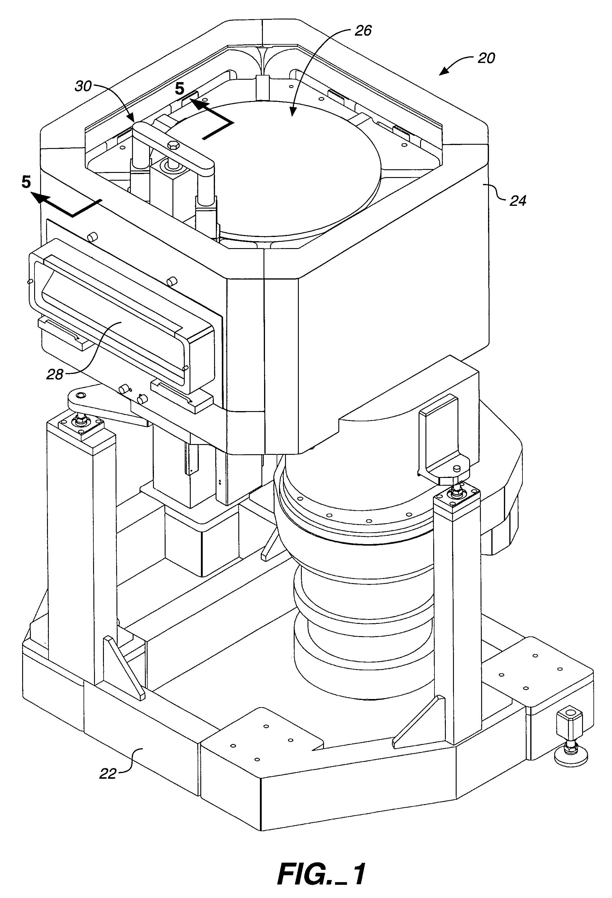
[0023]FIG. 1 shows a perspective view of a typical semiconductor wafer processing chamber 20. A frame 22 supports a chamber body 24. The chamber body 24 at its front side has a slit valve passage 28 with an outer slit valve door (that cannot be seen in FIG. 1) to seal the chamber and a chamber top assembly 26. Adjacent to the chamber top assembly 26 is an inner slit passage door actuator assembly 30 shown with its cover removed. Note that the inner slit passage door actuator assembly 30 is on the same side of the chamber body 24 as the slit valve passage 28 and the outer slit valve door (which cannot be seen) through which wafers are passed into and out of the chamber 20.

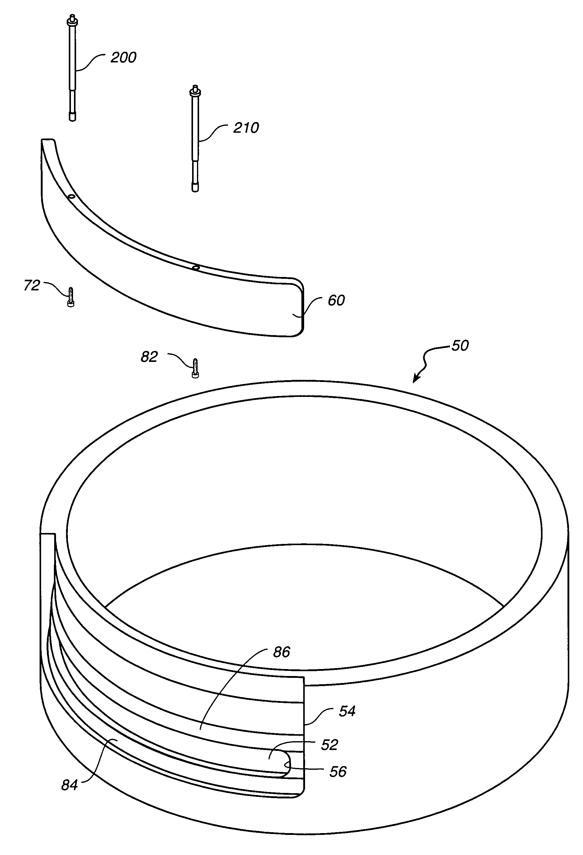
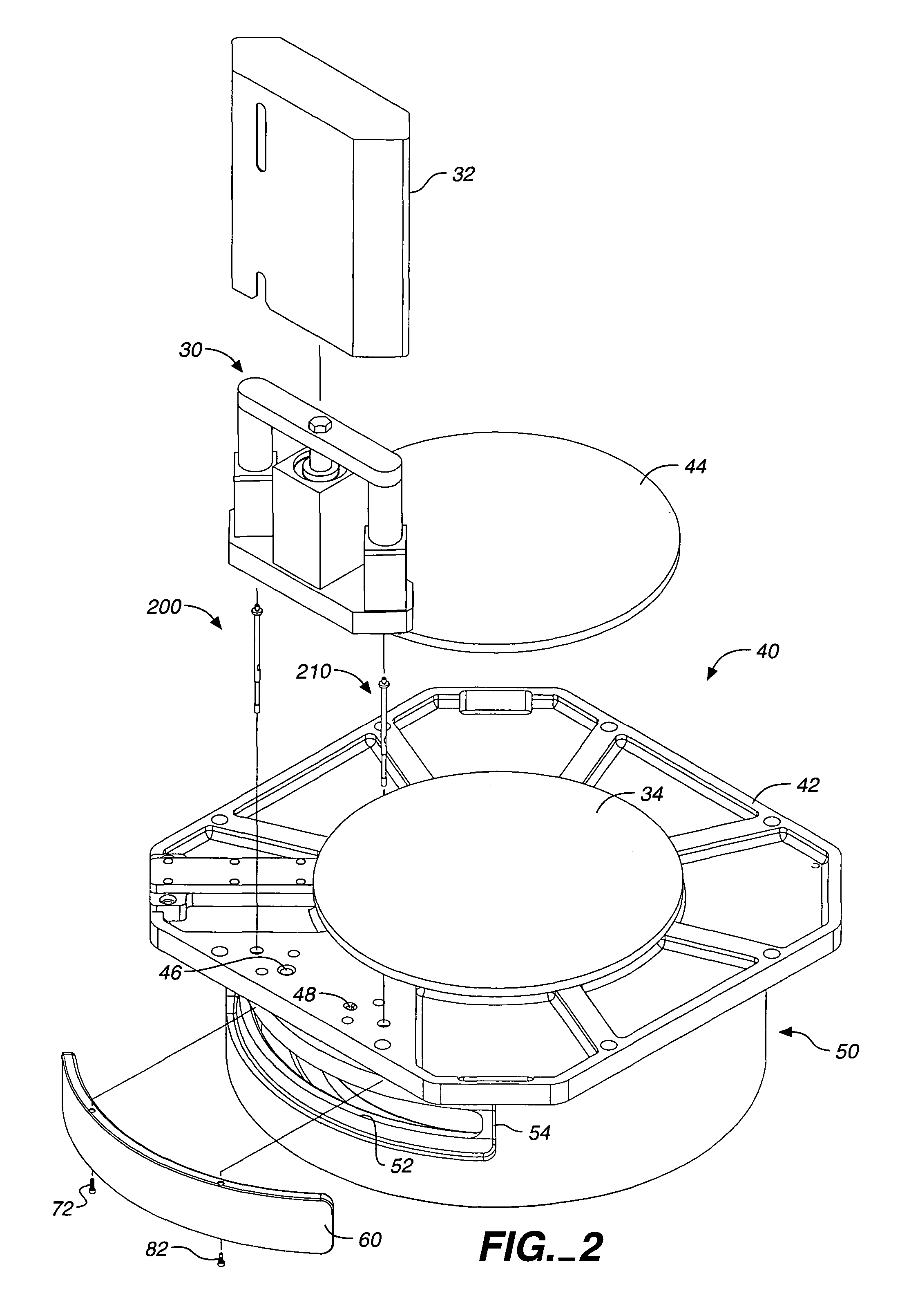
[0024]FIG. 2 is a partially exploded perspective view of the chamber liner and top assembly 40 including the inner slit passage door actuator assembly 30. A chamber top plate (or flange) 42 at its center supports a top plate electrode cover 44 and on the side adjacent the slit valve passage supports the inner slit p...


PUM

PropertyMeasurementUnit
pressureaaaaaaaaaa
pressureaaaaaaaaaa
circumferential widthaaaaaaaaaa

Abstract

In a substrate vacuum processing chamber, a second inner slit passage door apparatus and method to supplement the normal slit valve and its door at the outside of the chamber. The inner slit passage door, blocks the slit passage at or adjacent the substrate processing location in a vacuum processing chamber to prevent process byproducts from depositing on the inner surfaces of the slit passage beyond the slit passage door and improves the uniformity of plasma in the processing chamber by eliminating a large cavity adjacent to the substrate processing location into which the plasma would otherwise expand. The inner slit passage door is configured and positioned in such a way as to avoid generating particles from the opening and closing motion of the second slit valve door, as it does not rub against any element of the chamber during its motion and the inner slit passage door is positioned with a predetermined gap from adjacent pieces and the door configuration includes beveled surfaces to further reduce the chance for particle generation, even when there is deposition of process byproducts on the door and its adjacent surfaces.

Description

CROSS REFERENCE TO RELATED APPLICATIONS[0001]This patent application is a continuation of application Ser. No. 09 / 711,191 filed Nov. 13, 2000 now U.S. Pat. No. 6,647,918, which is a divisional of application Ser. No. 09 / 111,251 filed Jul. 3, 1998, now U.S. Pat. No. 6,192,827.FIELD OF THE INVENTION[0002]This invention relates to the construction of vacuum processing chambers used in processing of substrates for deposition and removal of materials. A particular chamber configuration using a specialized liner is disclosed.BACKGROUND OF THE INVENTION[0003]In general, vacuum processing chambers for processing substrates include a substrate transfer opening, commonly known as a slit valve. A slit passage associated with the slit valve is commonly used to transfer substrates into and out of the processing chamber between processing cycles. Commonly a robot extends from a cluster tool through a slit valve opening through the slit valve passage to deliver or remove a substrate to be processe...

Claims


Application Information

Patent Timeline
Patent Type & Authority Patents(United States)
IPC IPC(8): H01L21/00C23C16/00F16K51/02H01J37/20H01J37/32H01L21/205H01L21/302H01L21/3065
CPCH01J37/32458H01L21/67011H01J2237/186Y10S414/139Y10S156/916H01L21/00
Inventor WELCH, MICHAEL D.SHAN, HOMGQINGLUSCHER, PAUL E.LEE, EVANS Y.CARDUCCI, JAMES D.SALIMIAN, SIAMAK
Owner APPLIED MATERIALS INC
Why Eureka
Try Eureka