Method and system for resistance seam welding of a foil and at least one foil support of a fuel cell system

a fuel cell and foil technology, applied in the direction of resistance welding apparatus, hydrogen/synthetic gas production, organic chemistry, etc., can solve the problems of pressing and rolling movement of the roller electrode to damage the thin foil, and achieve the effect of increasing the permeation ra

Inactive Publication Date: 2006-12-12
DAIMLER AG
View PDF12 Cites 8 Cited by
  • Summary
  • Abstract
  • Description
  • Claims
  • Application Information

AI Technical Summary

Benefits of technology

[0007]An object of the present invention is to develop a method and a system for resistance seam welding of a foil and at least one foil support of a fuel cell system which reduce the leak rate for carbon monoxide during use in a diaphragm module and improve on the reliability of the fuel cell system.
[0009]According to the present invention, in seam welding of a foil and at least one foil support, foil and foil support are moved together relative to a roller electrode while resting on a flat support element. Prior to welding, the foil is mechanically fixed on the support element using one or two foil carriers or foil frames. A positioner having a welding strip is preferably provided as the support element. The foil does not come in contact with the roller electrode during welding. The roller electrode rolls on the relatively thick foil frame located on top, the foil remaining flat on the positioner or fixed between the two foil frames. This makes it impossible for the pressing and the rolling movement of the roller electrode to damage the thin foil. The pressing forces are absorbed by the foil frame which is in contact with the roller electrode. During welding, the support element or the positioner may be moved relative to the stationary axis of the roller electrode, or the roller electrode is moved along the stationary support element. If multiple parallel linear seams are to be produced, a corresponding number of roller electrodes arranged in parallel may be provided and simultaneously supplied with current. In order to avoid creases and buckles in the foil, the welded workpieces may be subjected to a heat treatment. For increasing the permeation rate, annealing in vacuum or under an inert gas or under pure hydrogen may follow the welding process. Foil supports and foils welded in this way allow for the lightweight design of hydrogen separation modules.

Problems solved by technology

This makes it impossible for the pressing and the rolling movement of the roller electrode to damage the thin foil.

Method used


Image

  • Method and system for resistance seam welding of a foil and at least one foil support of a fuel cell system
  • Method and system for resistance seam welding of a foil and at least one foil support of a fuel cell system
  • Method and system for resistance seam welding of a foil and at least one foil support of a fuel cell system

Examples


Embodiment Construction

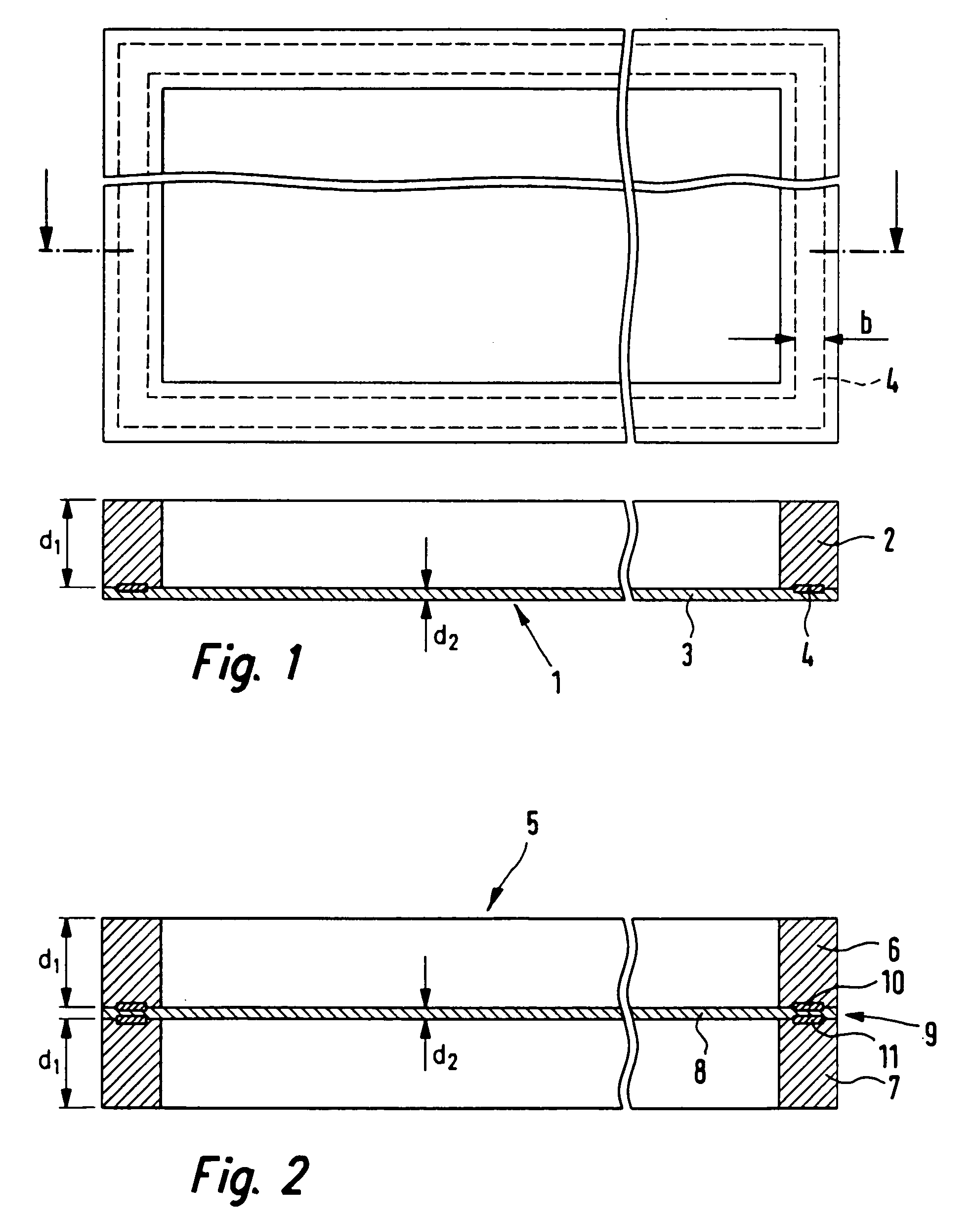
[0016]The schematic representation of a welding group 1 in FIG. 1 shows, in top view and sectional view, a foil frame or foil support 2 and a foil 3 which are welded together for use in a fuel cell system. Weld seam 4 of width b runs peripherally and concentrically to foil frame 2 which has the same outer dimensions as foil 3. Foil frame 2 has a thickness d1=200 μm and is made of a ferritic material such as austenitic steel or nickel. Foil 3 has the thickness d2=10 μm. Thickness d2 of foil 3 may vary depending on the application. Further practical thicknesses are 18 μm or 25 μm. Foil 3 is suited for hydrogen separation in a reformer module of the fuel cell system and is made, for example, of a palladium- and copper-containing alloy. Other alloys are also possible. Weld seam 4 connects foil 3 and foil frame 2 so tight together that there is a leak rate of smaller than 10−7 mbar*liter / second or that less than 40 ppm of carbon monoxide is present in the anode gas flow.

[0017]FIG. 2 show...


PUM

PropertyMeasurementUnit
time periodaaaaaaaaaa

Abstract

A method and a system for resistance seam welding of a foil and at least one foil support of a fuel cell system. During welding, the thin foil, together with the thicker foil support, is moved relative to the roller electrode while resting on a flat support element. In a suitable welding system, a counter-electrode is designed as a flat support element, such as a welding strip, that is displaceable relative to the roller electrode, the roller electrode being in rolling contact with the foil support, but not with the foil. Depending on whether one foil is to be welded to one or two foil frames, the support element may be designed having a high or a low specific electric resistance.

Description

[0001]Priority is claimed to German Patent Application No. DE 103 06 235.1, filed on Feb. 14, 2003, the entire disclosure of which is incorporated by reference herein.BACKGROUND[0002]The present invention relates to a method and a system for resistance seam welding of a foil and at least one foil support of a fuel cell system.[0003]Diaphragm modules which contain metal separation diaphragms or foils are used in fuel cells which are operated using hydrogen which is extracted from hydrocarbons, methanol, for example. At low permeation rates metal separation foils function selectively and in a temperature-stable manner. In selective separation of hydrogen via a metal separation foil, the permeation rate depends on the foil material, the pressure, the temperature, and the foil thickness. The temperature range is generally between 250° C. and 450° C. No noteworthy hydrogen separation occurs below 250° C. Intermetallic structural transformations, which drastically deteriorate permeation, ...

Claims


Application Information

Patent Timeline
Patent Type & Authority Patents(United States)
IPC IPC(8): B23K11/06B01D65/00B01D71/02B23K11/00B23K11/30C01B3/50H01M8/06
CPCB01D65/003B01D71/022B23K11/0033B23K11/061B23K11/3009B23K11/3018C01B3/505B23K2203/18C01B2203/041C01B2203/047H01M8/0606B23K2103/08B23K2103/12B23K2103/18B23K2103/22B23K2103/26Y02E60/50
Inventor BEISSWENGER, THOMASLAMM, ARNOLDPOSCHMANN, THOMASVOGEL, BERNHARDWEGER, WOLFGANGWIESHEU, NORBERT
Owner DAIMLER AG
Why Eureka
Try Eureka