DC-DC converter circuit, power supply selection circuit, and apparatus useful for increasing conversion efficiency

Inactive Publication Date: 2006-12-12
FUJITSU CLIENT COMPUTING LTD
View PDF17 Cites 20 Cited by
  • Summary
  • Abstract
  • Description
  • Claims
  • Application Information

AI Technical Summary

Benefits of technology

[0044]The apparatus of the present invention as mentioned above is provided with two DC-DC converters of the first and second DC-DC converters. The second DC-DC converter, which outputs the lower DC voltage, is arranged with the first

Problems solved by technology

A DC-DC converter circuit is associated with such disadvantages that a great deal of useless electric power is consumed for conversion of DC voltage, and as a result, the consumption of battery charge is hastened, and also this is associated with a temperature rise of the apparatus.
Particularly, in

Method used


Image

  • DC-DC converter circuit, power supply selection circuit, and apparatus useful for increasing conversion efficiency
  • DC-DC converter circuit, power supply selection circuit, and apparatus useful for increasing conversion efficiency
  • DC-DC converter circuit, power supply selection circuit, and apparatus useful for increasing conversion efficiency

Examples


second embodiment

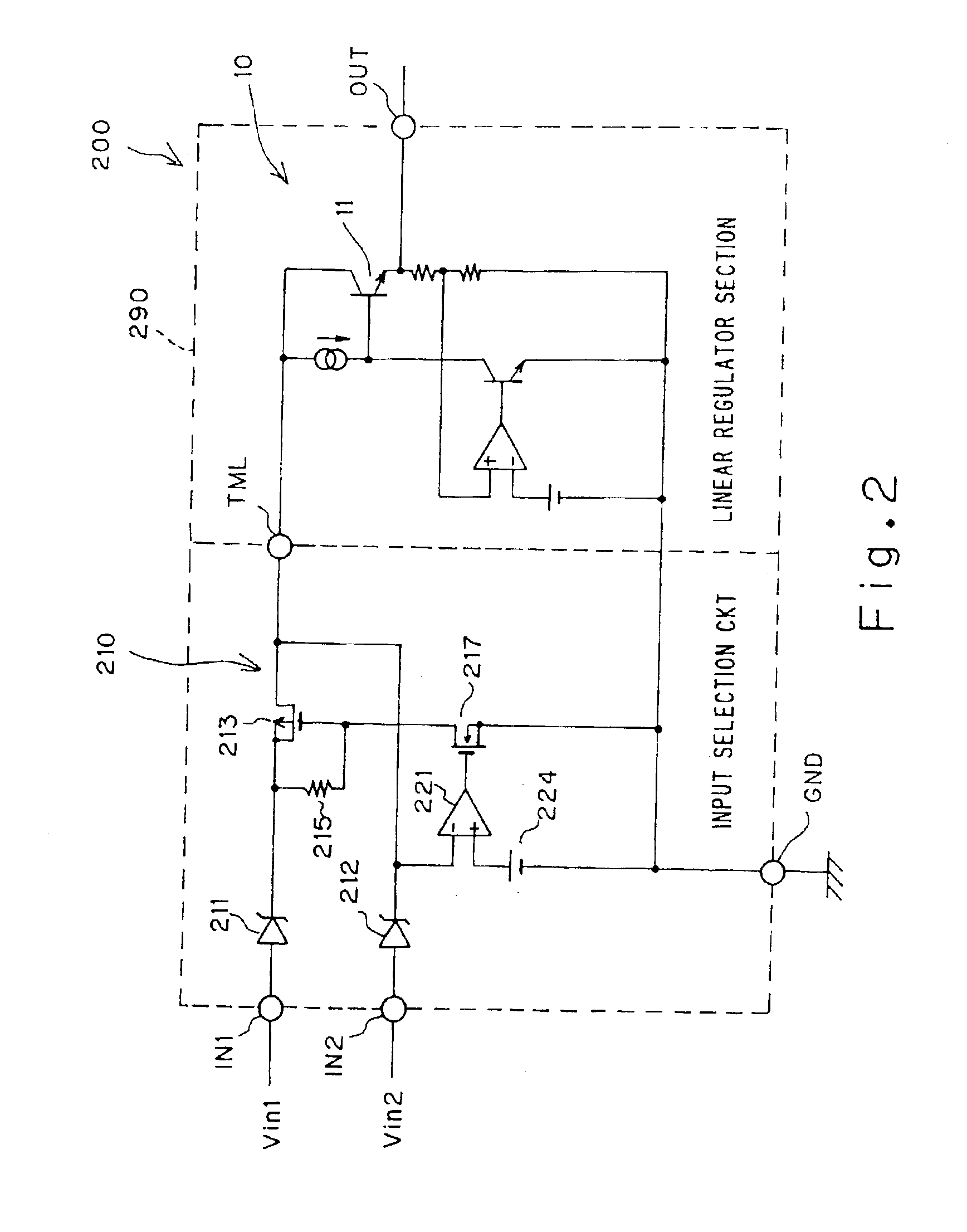
[0085]The operation of the circuit is the same as that of the second embodiment shown in FIG. 2, and thus redundant explanation will be omitted. The reason why the transistor 11 is disposed outside the LSI chip 390 is as follows. The DC-DC converter circuit 300 is of a large current capacity so that the secondary end thereof is permitted to consume a very large electric power, and thus as the transistor 11, there is a need to use a transistor which is capable of withstanding consumption of the large electric power. In view of the above-mentioned matter, a large capacity of transistor is needed as the transistor 11, and in addition, there is a need to perform a heat radiation by installing, for example, a heat sink and the like. That is, the transistor 11 is not suitable for incorporation into the LSI chip.

[0086]Thus, in a DC-DC converter circuit of a linear regulator scheme, it happens that a transistor for the output voltage control is mounted outside.

fourth embodiment

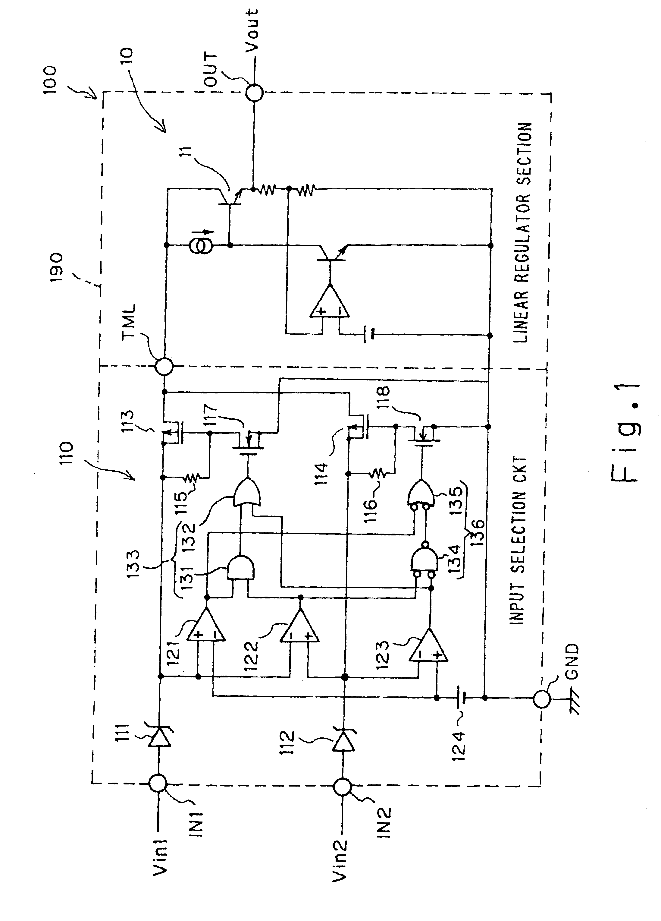
[0087]FIG. 4 is a circuit diagram of a DC-DC converter circuit according to the present invention.

first embodiment

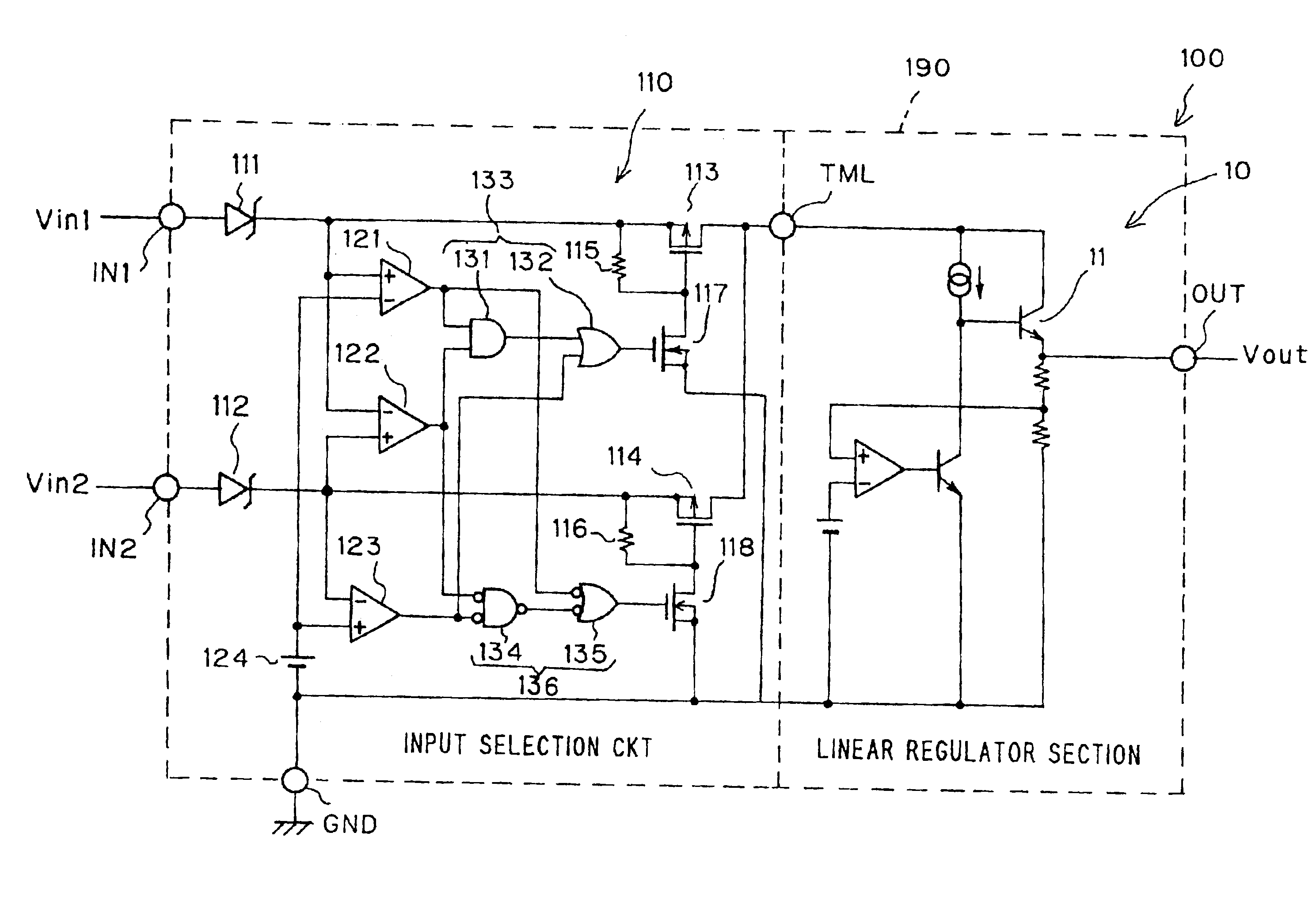
[0088]A DC-DC converter circuit 400 shown in FIG. 4 also comprises an input selection circuit 110, which is the power supply selection circuit of the present invention also shown in FIG. 1, and a switching regulator section 20 which is the same as the switching regulator shown in FIG. 10. The circuit operation of the input selection circuit 110 and the switching regulator section 20 has been already explained, and thus redundant explanation is omitted. The DC-DC converter circuit 400 shown in FIG. 4 is loaded on an LSI chip 490, except for a coil 31 and a capacitor 32, which are part of the switching regulator 20. The coil 31 and the capacitor 32 are considerably large and are not suitable for placement on the LSI chip.

[0089]The input selection circuit 110 receives two input voltages Vin1 and Vin2 (it is acceptable that either of the input voltages Vin1 and Vin2 may be a low voltage) applied through the two input terminals IN1 and IN2, respectively. Of the two input voltages Vin1 an...


PUM


Abstract

In a DC-DC converter circuit having a plurality of input terminals connected to a plurality of DC power supplies, and an output terminal, the DC-DC converter circuit includes a power supply selection section for selecting a DC power supply of lowest voltage on the condition that the voltage is not less than a predetermined voltage, and a step-down type of regulator section for converting the voltage of the DC power supply selected by the power supply selection section into a predetermined voltage lower than the voltage of the DC power supply selected by the power supply selection section, and outputting the converted voltage through the output terminal.

Description


Claims


Application Information

Patent Timeline
Owner FUJITSU CLIENT COMPUTING LTD
Why Eureka
Try Eureka