Electron beam system and electron beam measuring and observing methods

a technology of electron beam and electron beam, which is applied in the direction of material analysis using wave/particle radiation, instruments, nuclear engineering, etc., can solve the problems of long time to complete the photographing, the image processing is difficult, and the image processing is easier. , to achieve the effect of accurately obtaining the shape or coordinate value of the sample, and avoiding the distortion of the electron beam or magnification distortion derived from the tilt angle and heigh

Inactive Publication Date: 2006-12-19
KK TOPCON
View PDF4 Cites 21 Cited by
  • Summary
  • Abstract
  • Description
  • Claims
  • Application Information

AI Technical Summary

Benefits of technology

[0023]In an electron beam system, as shown in FIG. 23, for example, the reference image selecting section 40 selects one of the right and left images for a stereo image obtained from the electron beam detecting section 4 as a reference image. As the photographing object, a sample having reference points the positions of which have been known in advance such as a reference target. As the photographing attitude, tilt states suitable to photograph the sample are selected. The first correction factor measuring section 44 obtains a first image correction factor which distorts the non-reference image into the distortion state of the reference image. As the photographing object, a reference target is used. The first image converting section 46 converts the non-reference image using the first image correction factor into an image having distortion similar to that of the reference image. As the photographing object, a sample as a measuring object is used. The image coordinate transforming section 48 performs a coordinate transformation of the reference image and an image converted from the non-reference image to images which can be obtained when the relative tilt angle created by the sample tilting section 5 is in a standard state (for example the state of 0 degree tilt angle of the holder 3 with the electron beam 7 perpendicular to the holder). Since image distortion is not corrected in the coordinate transformation, the image processing in the coordinate distortion is easier that that in the image conversion. Also, since coordinate conversion into images which can be obtained in a standard state is performed, images of the sample photographed in tilt states can be used easily. The coordinate measuring section 52 obtains the shape or coordinate values of the sample included in a stereo image composed from the non-reference image and reference image which have been subjected to a coordinate transformation in the image coordinate transforming section 48.
[0024]Preferably, the electron beam system of this invention also comprises, as shown e.g. in FIG. 22, a second image converting section 54 for converting the reference image and the non-reference image which have been subjected to a coordinate transformation in the image coordinate transforming section 48, using a second image correction factor for removing the distortion in the reference image with respect to an image which can be obtained when the relative tilt angle created by the sample tilting section 5 is in a standard state, and the coordinate measuring section 52 obtains the shape or coordinate values of the sample included in a stereo image composed of images converted from the reference image and the non-reference image in the second image converting section 54. Since the distortion in images photographed in tilt states suitable to photograph the sample and the distortion in an image photographed when the relative tilt angle created by the sample tilting section 5 is in a standard state are different from each other in the electron beam device 10, when an image obtained when the relative tilt angle created by the sample tilting section 5 is in a standard state is corrected using the first image correction factor obtained in the first correction factor measuring section 44, image distortion may not be sufficiently corrected. When the second image converting section 54 corrects the non-reference image and the reference image which have been subjected to a coordinate transformation in the image coordinate transforming section 48, using the second image correction factor, the coordinate measuring section can accurately obtain the shape or coordinate values of the sample.
[0025]Preferably, the electron beam system of this invention also comprises, as shown e.g. in FIG. 30, a third image converting section 55 for converting the reference image and an image converted from the non-reference image in the first image converting section 46 using a third image correction factor for removing image distortion in the reference image with respect to an image which can be obtained when the relative tilt angle created by the sample tilting section is in a standard state, and the image coordinate transforming section 48 performs a coordinate transformation of images converted from the reference image and the non-reference image in the third image converting section 55 into images which can be obtained when the relative tilt angle created by the sample tilting section 5 is in a standard state. Since the distortion in images photographed in tilt states suitable to photograph the sample and the distortion in an image photographed when the relative tilt angle created by the sample tilting section 5 is in a standard state are different from each other in the electron beam device 10, when an image obtained when the relative tilt angle created by the sample tilting section 5 is in a standard state is corrected using first image correction factor obtained in the first correction factor measuring section 44, image distortion may not be sufficiently corrected. When the third image converting section 55 corrects, using the third image correction factor, the reference image and an image converted from the non-reference image in the first image converting section 46, and when the image coordinate transforming section 48 performs a coordinate transformation of the images converted from the reference image and non-reference image in the third image converting section 55 into images which can be obtained when the relative tilt angle created by the sample tilting section 5 is in a standard state, the coordinate measuring section can accurately obtain the shape or coordinate values of the sample.

Problems solved by technology

In measuring a sample such as a semiconductor chip or a silicone wafer, however, electron beam distortion or magnification distortion derived from the tilt angle and height of the sample is involved.
However, when a measuring object is photographed from many angles, it takes long to complete the photographing and the throughput of semiconductor fine processing is decreased.

Method used


Image

  • Electron beam system and electron beam measuring and observing methods
  • Electron beam system and electron beam measuring and observing methods
  • Electron beam system and electron beam measuring and observing methods

Examples


first embodiment

[First Embodiment]

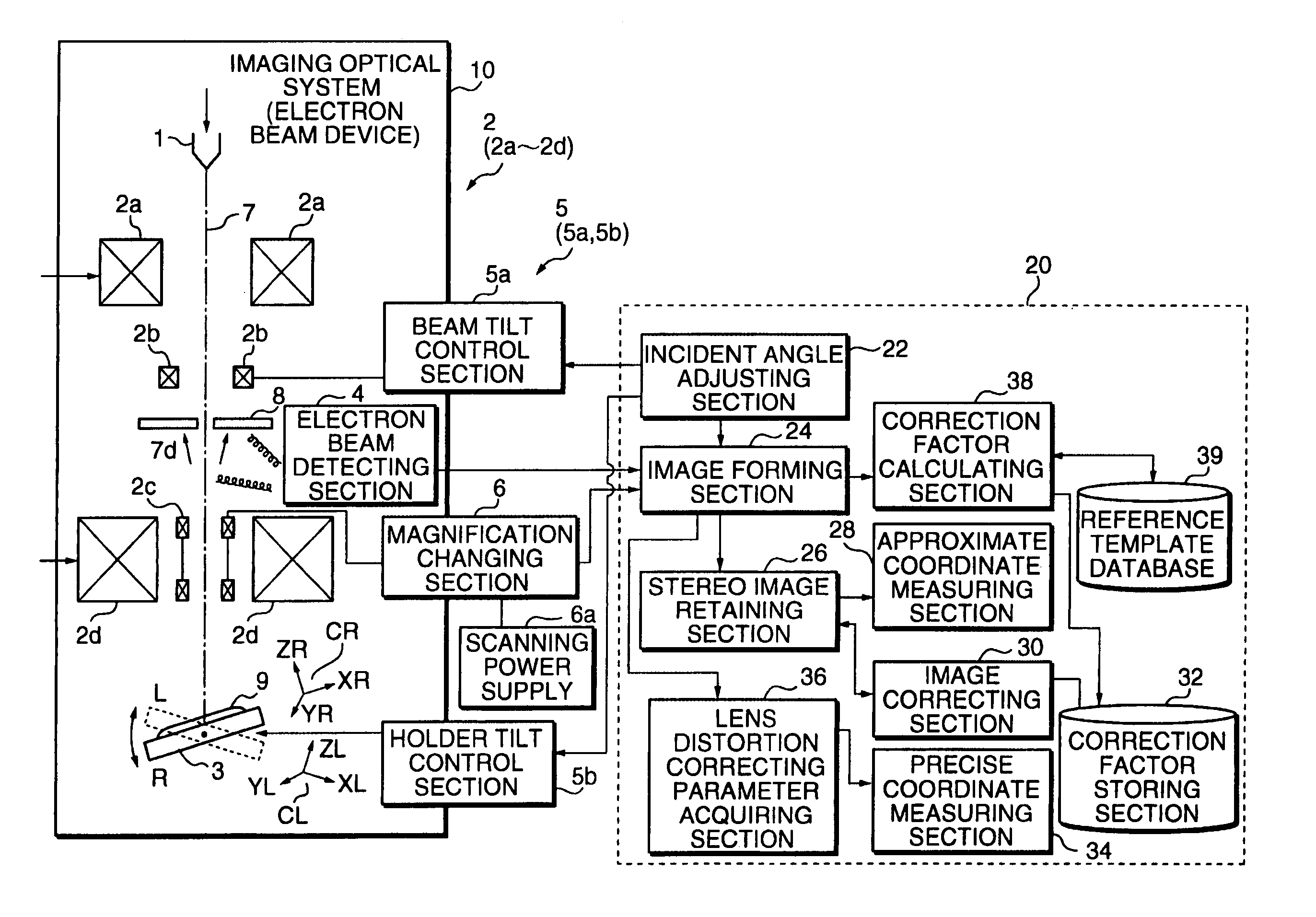
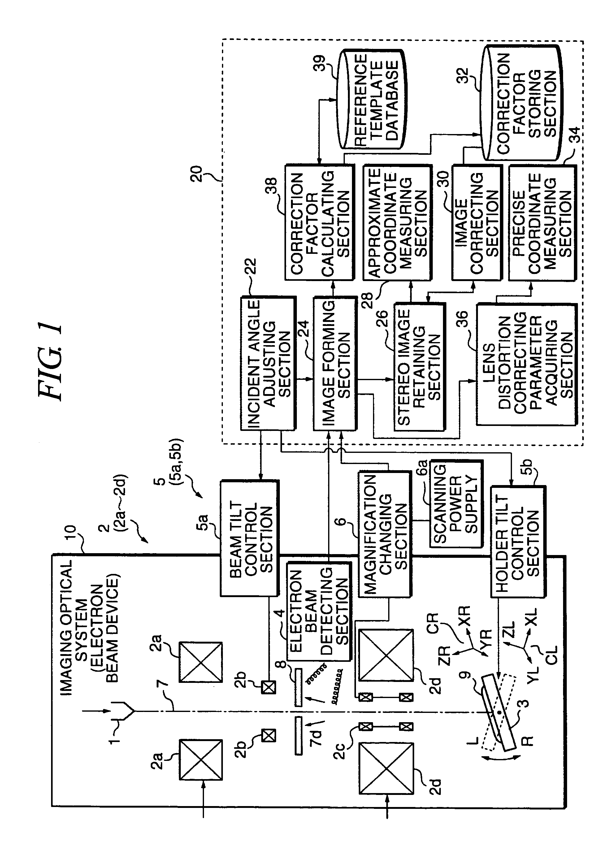
[0087]Description will be hereinafter made of the embodiments of this invention with reference to the drawings. FIG. 1 is a block diagram illustrating the structure of a first embodiment of this invention. In the first embodiment, the rotational angle of the holder for holding an object is adjusted to adjust the tilt angle of the object so that a stereo image of the object can be obtained. As shown in the drawing, an electron beam device 10 (scanning electron microscope) as an imaging optical system has an electron beam source 1 for emitting an electron beam 7, an electron optical system 2 for irradiating the electron beam 7 on an object 9, a sample holder 3 for tiltably holding the object 9, a magnification changing section 6 for changing the magnifying power of the electron optical system 2, a scanning power supply 6a for supplying electric power to the magnification changing section 6, a detector 4 for detecting the electron beam 7, a holder tilt control section...

second embodiment

[Second Embodiment]

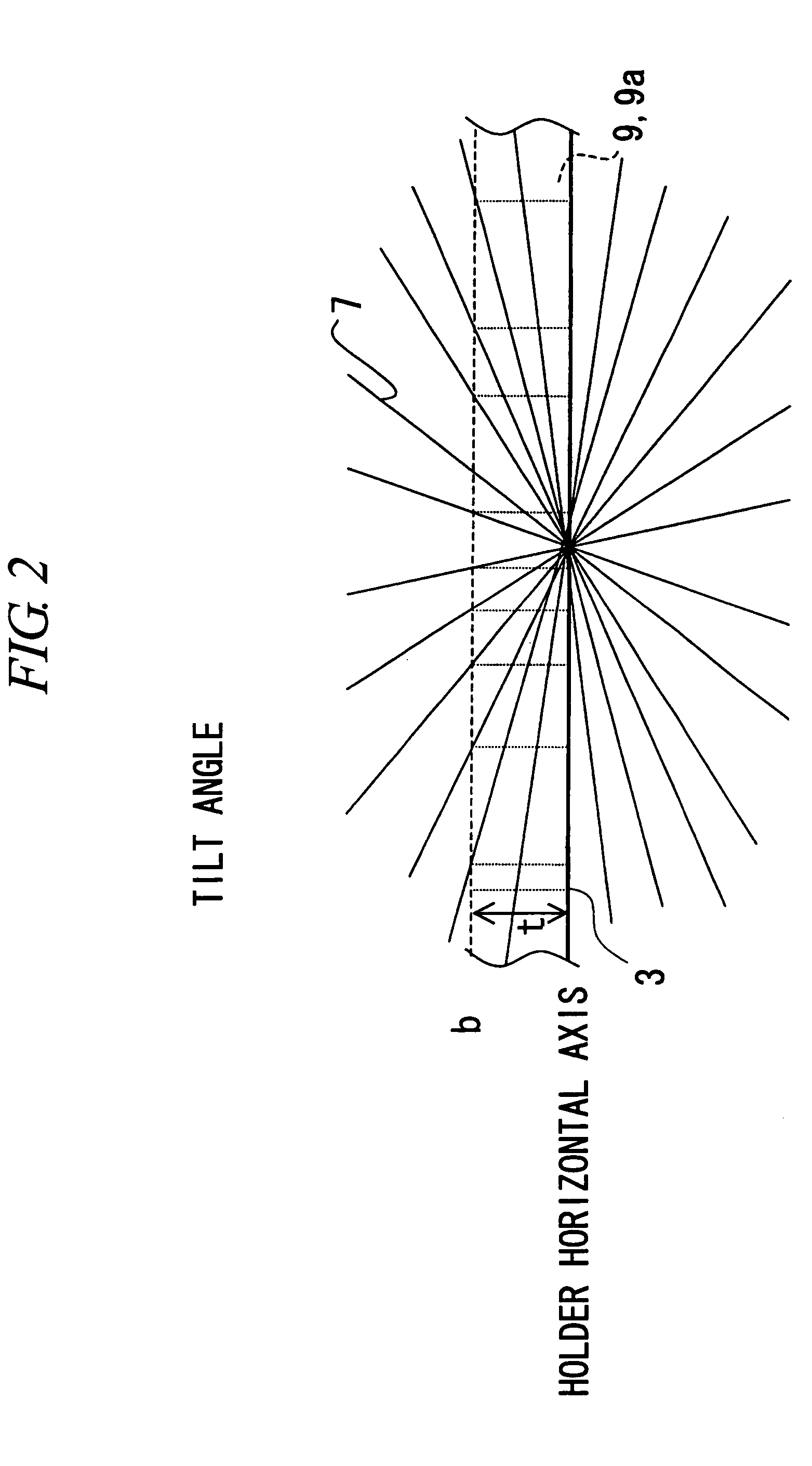
[0128]Referring now to FIG. 19, a case will be described in which a three-dimensional template is used as a reference template. The process is generally the same as in the first embodiment except that the procedure for obtaining the height correcting parameters is suitable for a three-dimensional reference template. FIG. 19 is a flowchart used to explain the process of photographing and acquiring images of a three-dimensional reference template. A three-dimensional reference template 9c is placed on the sample holder 3 (S400). Then, the holder tilt angle control section 5b sends a tilt control signal to the sample holder 3 and the incident angle adjusting section 22 adjusts the incident angle of the electron beam 7 relative to the object 9 (S410). When the reference template 9c is three-dimensional, the interval between the tilt angles may be large or coarse as has been described with FIG. 9. The tilt angles which the incident angle adjusting section 22 sets in st...

third embodiment

[Third Embodiment]

[0132]Description will be made of a third embodiment with reference to FIG. 20. The third embodiment relates to the procedure for observing a sample with images thereof photographed by the electron beam device 10 using the height correcting parameters obtained in the first or second embodiment. FIG. 20 is a flowchart used to explain the procedure for observing a sample with images of the sample photographed by the electron beam device 10. A measuring object 9 is placed on the sample holder 3 (S500). The incident angle adjusting section 22 tilts the sample holder 3 at desired angles (S510). The tilt angles are determined based on what part of the measuring object 9 is necessary to be viewed or the required measurement accuracy. For example, the sample holder 3 and the electron beam 7 make the first and second tilt angles relative to each other. The electron beam measuring device 20 acquires stereo pair images of the measuring object 9 (S520). The stereo pair image d...


PUM


Abstract

To provide an electron beam system capable of performing three-dimensional measurement of a sample with high precision irrespective of the tilt angle and height of the sample. The electron beam system has a correction factor storing section 32 for storing a correction factor at a reference tilt angle with respect to a plane which is used to tilt a sample by a sample tilting section 5, an approximate coordinate measuring section 28 for obtaining an approximate shape or approximate coordinate values of the sample based on an output corresponding to a stereo image from an electron beam detecting section 4, an image correcting section 30 for correcting the stereo image according to the tilt angle created by the sample tilting section 5 based on the shape or coordinate values of the sample obtained in the approximate coordinate measuring section 28 using a correction factor stored in the correction factor storing section 32, and a precise coordinate measuring section 34 for obtaining a shape or coordinate values of the sample which are more precise than those obtained in the approximate coordinate measuring section 28 based on a corrected stereo image obtained in the image correcting section 30.

Description

BACKGROUND OF THE INVENTION[0001]1. Technical Field[0002]This invention relates to an electron beam system and an electron beam measuring and observing methods for performing three-dimensional measurement or three-dimensional observation of a sample with high precision using images of the sample photographed with an electron microscope.[0003]2. Related Art[0004]In the case of a transmission electron microscope (TEM), the sample is tilted to obtain transmission images at different tilt angles, and stereo observation is performed using the images as right and left images. In the case of a scanning electron microscope (SEM), the sample or the electron beam is tilted to obtain reflection images at different tilt angles, and stereo observation is performed using the images as right and left images as described in Non-patent Document 1. In the field of semiconductor producing equipment, an electron beam device and a data processing device for an electron beam device are proposed which are...

Claims


Application Information

Patent Timeline
Patent Type & Authority Patents(United States)
IPC IPC(8): H01J37/28
CPCH01J37/265H01J37/28H01J2237/221H01J2237/2611
Inventor KOCHI, NOBUOKOIKE, HIROTAMITSURUGA, YASUKOOKADA, SHINICHI
Owner KK TOPCON
Why Eureka
Try Eureka