
Method for efficient four-wave mixing generation and short pulse generation equipment using the method

a four-wave mixing and short-wave technology, applied in multiplex communication, instruments, cladded optical fibres, etc., can solve the problems of inability to allow too intense light to be launched into optical fibers, inability to shorten the length of optical fibers infinitely, and inability to intensify input pumping light without any restriction, etc., to achieve the effect of sufficient efficiency

Inactive Publication Date: 2006-12-26
FURUKAWA ELECTRIC CO LTD
View PDF19 Cites 11 Cited by
  • Summary
  • Abstract
  • Description
  • Claims
  • Application Information

AI Technical Summary

Benefits of technology

[0045]It is necessary to reduce the effect of PMD as much as possible when a broadband wavelength conversion or a broadband CPA is prepared using a highly nonlinear optical fiber, which is not of a polarization maintaining type. Therefore, it is thought that the effect of PPM due to PMD can be reduced by shortening the length of the fiber so as to make the smaller than the bandwidth of the principal state of polarization. In this case, the pumping light and the signal light are inputted in the same state of polarization with the state of the polarization being one of the principal states of polarization, thereby minimizing the degradation of the PPM efficiency due to different polarization.
[0048]According to the present invention, the four-wave mixing can be generated with sufficient efficiency when a fiberoptic device employing the four-wave mixing, which is a nonlinear effect in a optical fiber, especially such as a wavelength converter or an optical parametric amplifier as well as other fiberoptic devices employing the four-wave mixing. By using a short highly nonlinear optical fiber that satisfies the conditions evaluated here, it becomes possible to generate the four-wave mixing in a manner that makes the most of the feature of the pumping light by minimizing the stimulated Brillouin scattering, the mismatching the states of polarization between the pumping light and signal light due to the birefringence of the fiber, and the effect of fluctuation in wavelength dispersion in the longitudinal direction causing from actual manufacturing process of the optical fiber.

Problems solved by technology

However, when the aforementioned discussion is conducted, it is necessary to note that the input pumping light cannot be intensified without any restriction.
In addition, it is also impossible to allow too intense light to be launched into an optical fiber because of the stimulated Brillouin scattering (SBS).
Next, even with a highly nonlinear optical fiber, it is impossible to shorten the length of the optical fiber infinitesimally.
Therefore, it is impossible to obtain significant information regarding an optimum length of the fiber from the equation (1).
What is in particular meant here is the problem of the effects of PMD that deteriorates generating the efficient and broadband PPM.
Therefore, in the configuration such as the wavelength converting device or CPA, it is a critical problem how to coincide the state of polarization with each other.

Method used


Image

  • Method for efficient four-wave mixing generation and short pulse generation equipment using the method
  • Method for efficient four-wave mixing generation and short pulse generation equipment using the method
  • Method for efficient four-wave mixing generation and short pulse generation equipment using the method

Examples


embodiment 1

[Embodiment 1]

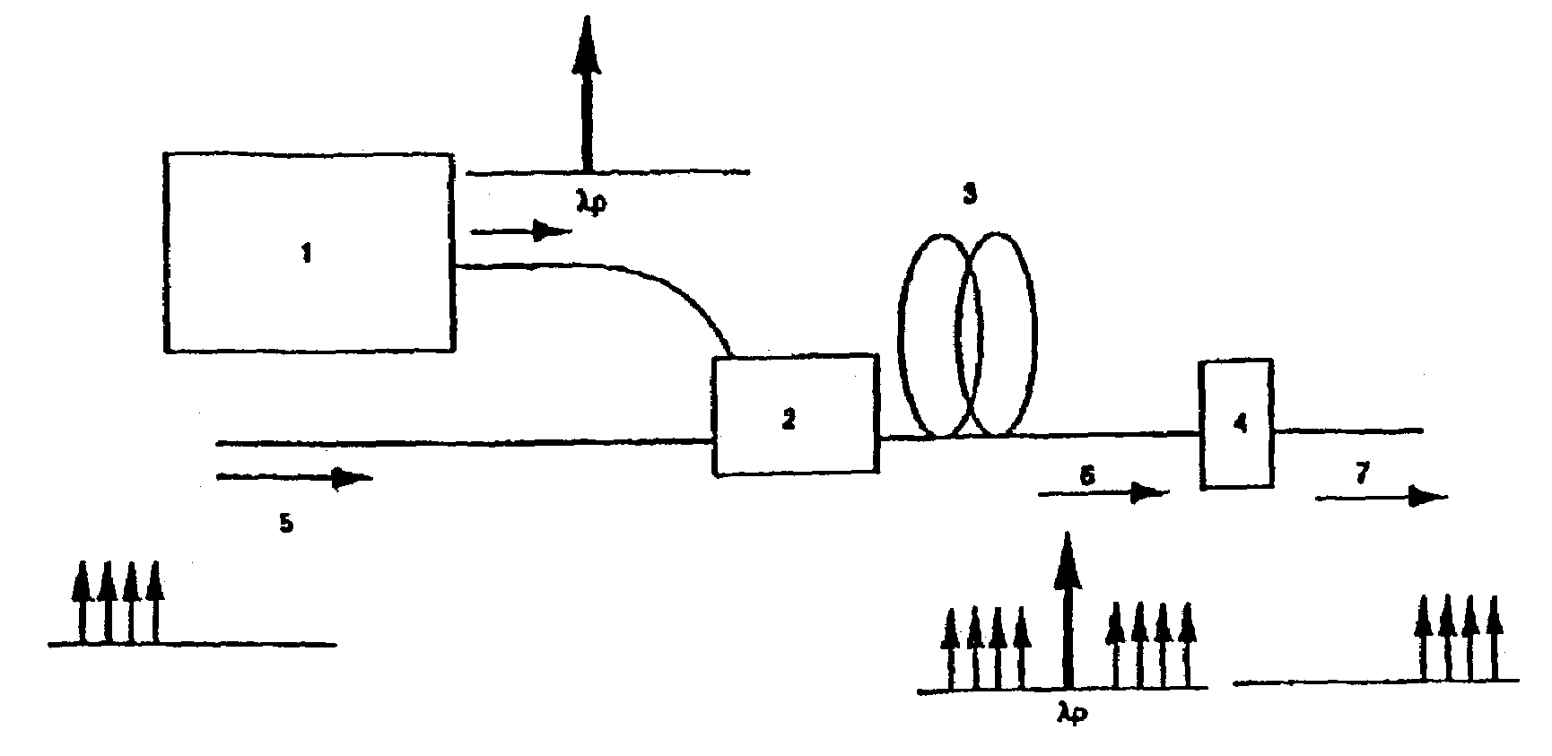
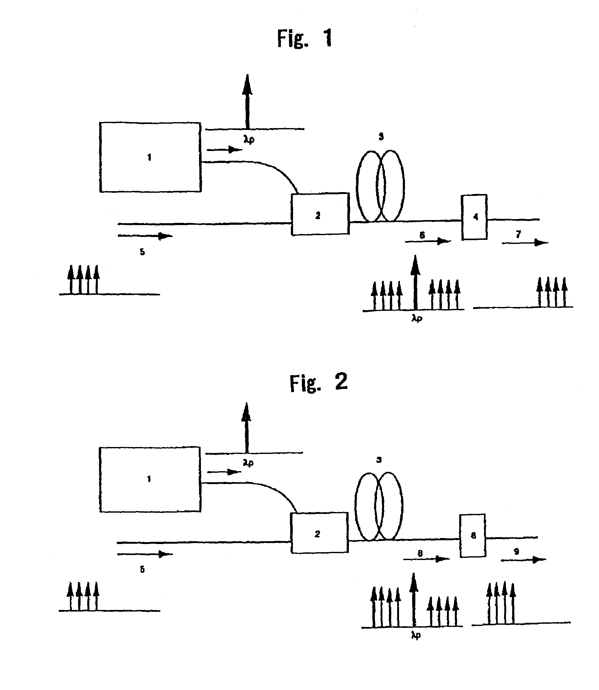
[0072]Embodiment 1 shows a form of a wavelength converter for implementing the present invention. FIG. 1 is a conceptual view showing a conceivable wavelength converter. Pumping light launched into a highly nonlinear optical fiber 3 from a pumping light source 1 is combined with a light signal 5 by an optical combiner 2. This combined light generates idler light in a highly nonlinear optical fiber 3 of which length is optimized. The wavelength of the signal light is converted by the FPM interaction into this idler light. Light 6 on the frequency axis of which all of the signal light, the pumping light, and the idler light are present is emitted from the output end of an optical fiber 3. Accordingly, a wavelength converter can be implemented by filtering the light 6 to obtain only the idler light 7 using an optical filter 4. Incidentally, the idler light 7 and the light signal 5 are phase conjugated, and thus this device serves also as a generator of an optical phase co...

embodiment 2

[Embodiment 2]

[0073]Embodiment 2 shows a form of an optical parametric amplifier for implementing the present invention. FIG. 2 is a conceptual view showing a conceivable optical parametric amplifier. Pumping light launched from a pumping light source 1 is combined with a light signal 5 by an optical combined 2. This combined light generates idler light in a highly nonlinear optical fiber 3 of which length is optimized, while the intensity of the signal light itself is being amplified by the parametric amplification effect. Light 6 on the frequency axis of which all of the amplified signal light, the pumping light, and the idler light are present is emitted from the output end of the optical fiber 3. Accordingly, an optical parametric amplifier can be implemented by filtering the light 6 to obtain only the amplified signal light 9 using an optical filter 8.

embodiment 3

[Embodiment 3]

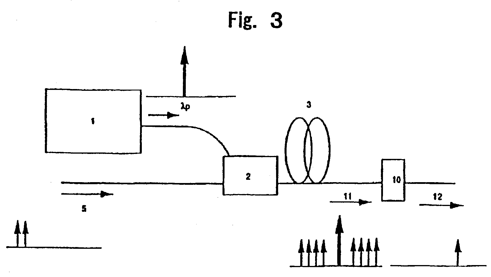
[0074]Embodiment 3 shows a form of an optical circuit to be used in an optical signal regeneration circuit for implementing the present invention. As described in literature [12], the optical regeneration circuit outputs an optical signal of which waveform is shaped with respect to an input signal light or extracts optical time division multiplexed signals. The optical circuit that constitutes the optical signal regeneration circuit shown in FIG. 2 of the literature [12] comprises, as shown in the specification of the literature [12], a highly nonlinear medium for generating four wave mixing, an optical filter for allowing only the idler light to pass therethrough, and a pumping light source. Therefore, the construction is the same as that of Embodiment 1. In the literature [12], a semiconductor amplifier was used as the highly nonlinear medium. By constituting the optical signal regeneration circuit shown in the literature [12] using the optical circuit of the configu...


PUM


Abstract

The present invention provides a method for generating four-wave mixing to obtain idler light with high efficiency, in which the range of lengths of an optical fiber is appropriately set, and probe light and pumping light, having different frequencies, are launched into the optical fiber. When the nonlinear coefficient of the optical fiber, the loss per unit distance, and the wavelength and intensity of the probe light and pumping light are set to certain values, the idler light conversion efficiency at the output end of the optical fiber is a periodic function of an optical fiber having a maximal value and a minimal value. The maximum length of the optical fiber to be used to obtain four-wave mixing is set to be equal to or less than the length Lmax (Lmax=Lm+ΔL) which is given by adding the length of the optical fiber Lm, at which the idler light conversion efficiency takes on the first maximal value in the aforementioned periodic function and distance ΔL or 10% of L.

Description

[0001]This application is a continuation-in-part application of application Ser. No. 09 / 536,713, filed Mar. 28, 2000 now U.S. Pat. No. 6,522,818, and is hereby incorporated by reference.FIELD OF THE INVENTION[0002]The present invention relates to a method for generating four-wave mixing and apparatus for short pulse generation using the method, which provides four-wave mixing in an optical fiber to generate frequency converted light and which is used in fiberoptic non-linear device such as a fiberoptic wavelength converter, a fiberoptic optical parametric amplifier, and a fiberoptic optical phase conjugation generator.BACKGROUND OF THE INVENTION[0003]The four-wave mixing in an optical fiber is generated, resulting from the third-order non-linear polarization of a fiber material. The present application discusses in particular the phenomenon in which idler light (converted light) of a frequency fc (=2fp−fs) is generated when probe light (or signal light) of a frequency fs and pumping...

Claims


Application Information

Patent Timeline
IPC IPC(8): G02B6/02G02B6/34G02F1/35
CPCG02F1/3536G02B6/2766G02F2201/02
Inventor ASO, OSAMUTADAKUMA, MASATERUNAMIKI, SHU
Owner FURUKAWA ELECTRIC CO LTD
Learn More