
Method for co-verifying hardware and software for a semiconductor device

a technology of semiconductor devices and hardware, applied in the direction of instrumentation, program control, cad circuit design, etc., can solve the problems of increasing simulation time, i.e., verification time, and achieve the effect of fast simulation execution and without degrading simulation accuracy

Inactive Publication Date: 2006-12-26
SEIKO EPSON CORP
View PDF23 Cites 15 Cited by
  • Summary
  • Abstract
  • Description
  • Claims
  • Application Information

AI Technical Summary

Benefits of technology

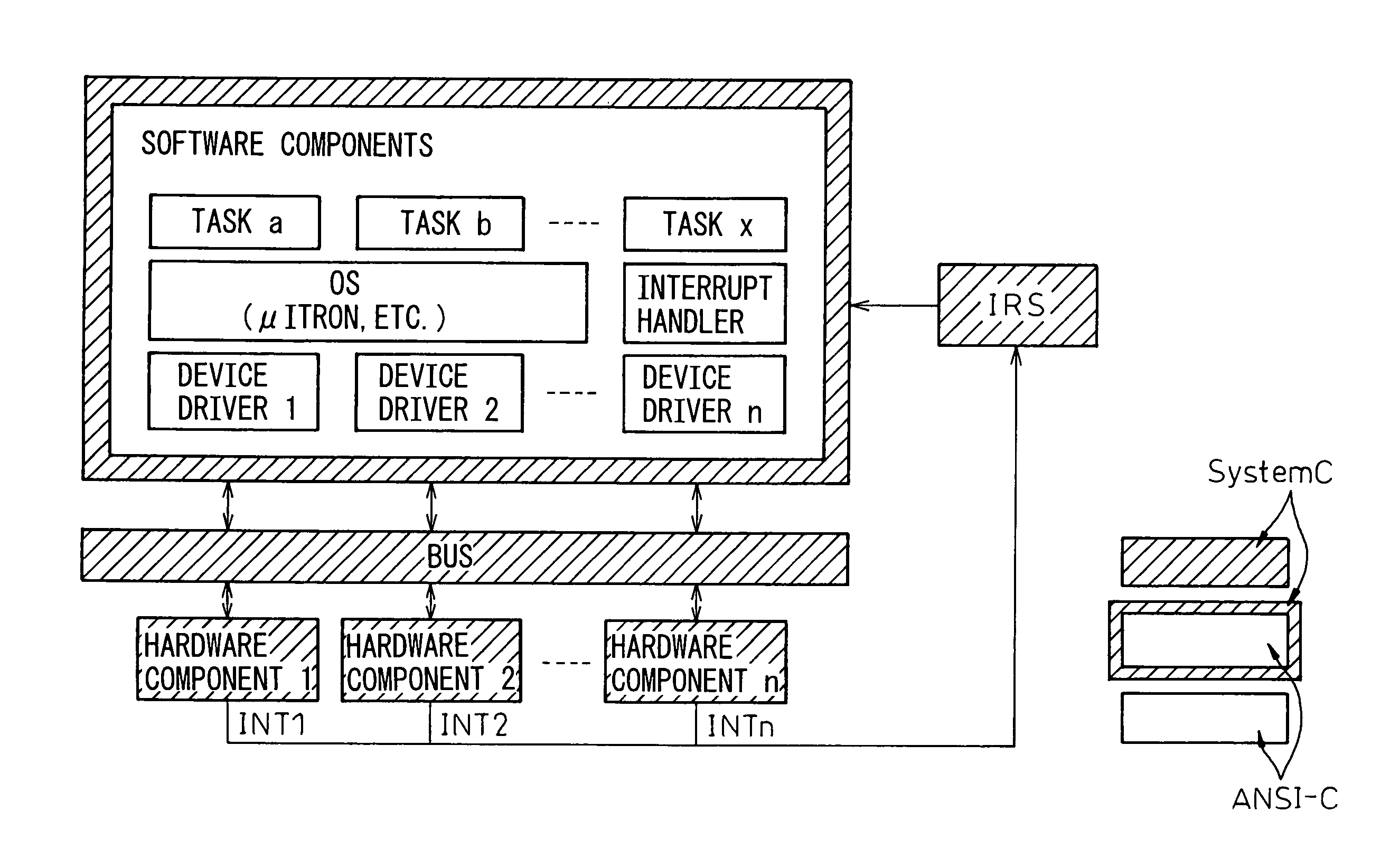
The present invention provides a hardware / software co-verification method that achieves fast simulation execution by implementing a C-based native code simulation that eliminates the need for per-instruction interpretation and execution with respect to timing. The method involves inputting a verification model of a timed software component and a hardware component in a C-based language, compiling them, and linking them together. A testbench is also inputted and compiled. A simulation is performed based on the compiled models, and the result of the simulation is outputted. The invention also provides a method for generating a timed software component from an untimed software component by recognizing basic blocks, inserting control points, computing execution time between control points, and inserting an execution time insertion statement at each control point.

Problems solved by technology

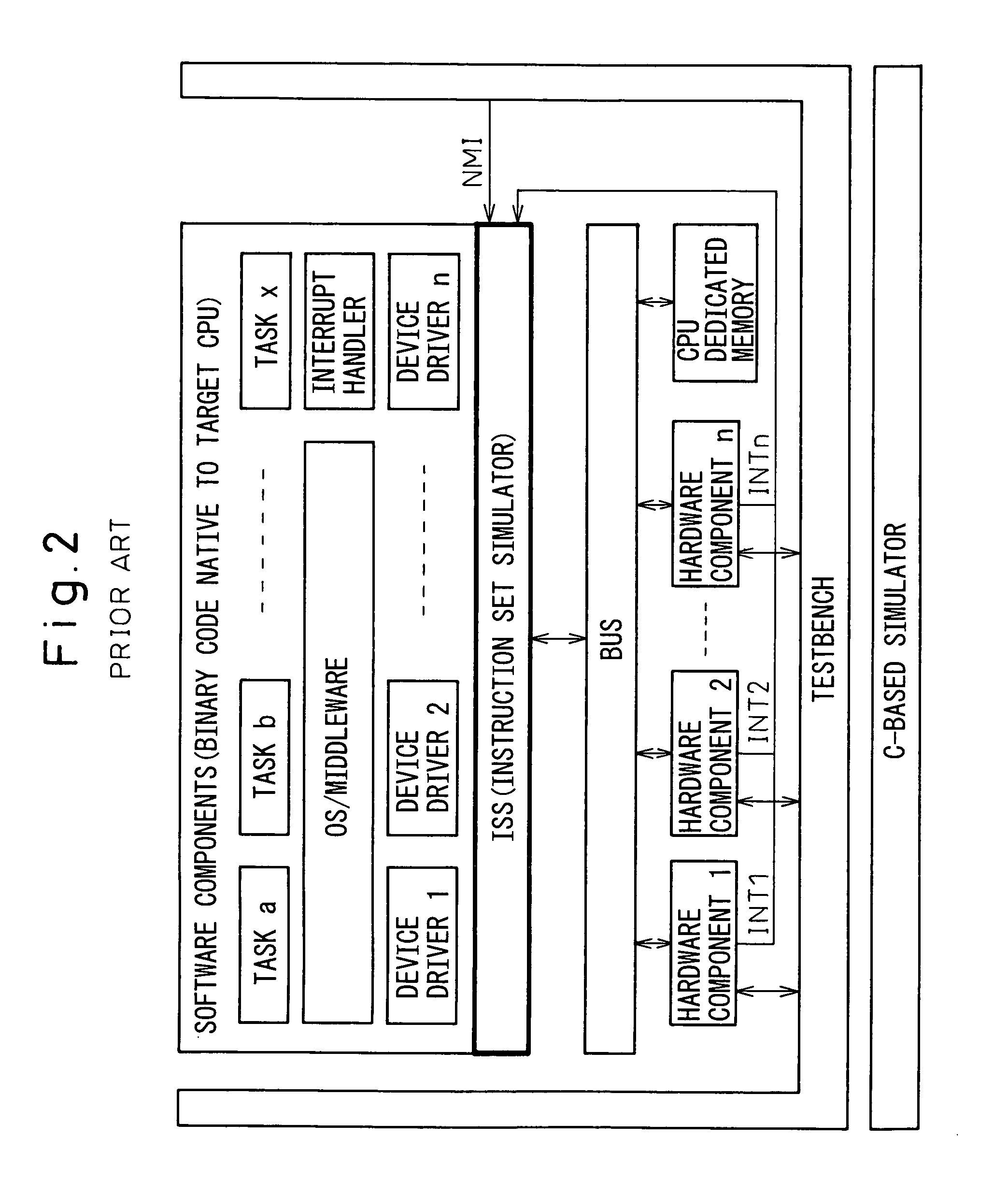
In the hardware / software co-verification methods using ISSs according to the prior art described above, as simulation is performed at the instruction level, that is, simulation is performed on an instruction-by-instruction basis by interpreting the contents of each instruction, which requires a memory access, the prior art involves the problem that the simulation time, i.e., the verification time, increases.

Method used


Image

  • Method for co-verifying hardware and software for a semiconductor device
  • Method for co-verifying hardware and software for a semiconductor device
  • Method for co-verifying hardware and software for a semiconductor device

Examples


Embodiment Construction

[0045]An embodiment of the present invention will be described below with reference to the accompanying drawings.

[0046]FIG. 3 is a diagram for explaining a hardware environment for implementing a hardware / software co-verification method according to the present invention. As shown as an example in the figure, co-verification according to the present invention can be run on a conventional personal computer (PC) or a workstation (WS), which comprises a computer main unit 10 having a central processing unit (CPU) 12 and a main storage (MS) 14, a display 20, a keyboard 22, a mouse 24, and an external storage 30 such as a hard disk drive.

[0047]The CPU 12 operates as a host CPU for executing the co-verification, and is, for example, a Pentium (registered trademark) processor. Programs for co-verification described hereinafter are executed by the CPU 12. Various kinds of data, files, etc. are loaded from the external storage 30 into the main storage (MS) 14 for processing.

[0048]Next, refer...


PUM


Abstract

A hardware / software co-verification method that achieves fast simulation execution by implementing a C-based native code simulation without degrading the accuracy of timing verification. This method is a method for co-verifying hardware and software, by using a host CPU, for a semiconductor device on which at least one target CPU and one OS are mounted wherein, first, a timed software component described in a C-based language or constructed from binary code native to the host CPU and a hardware component described in the C-based language are input as verification models, necessary compiling is performed, and the compiled components are linked together. Next, a testbench is input and compiled. Then, the components and the testbench are linked together, after which simulation is performed and the result of the simulation is output.

Description

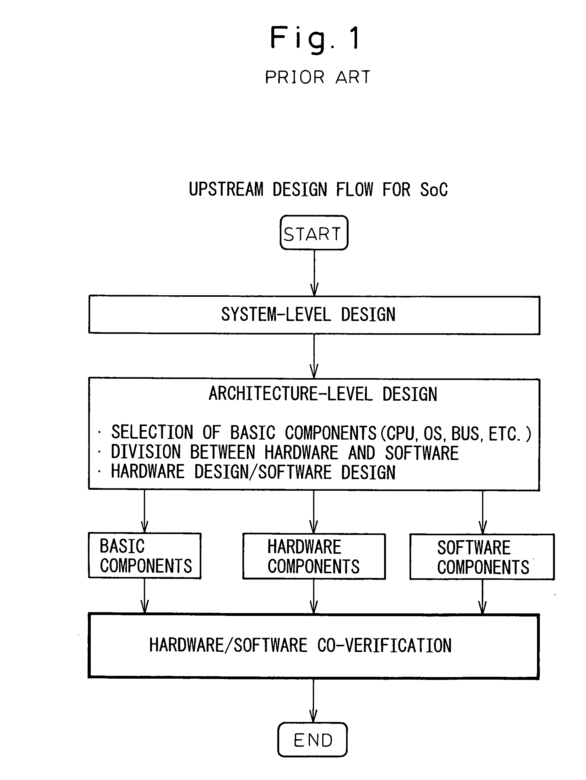
BACKGROUND OF THE INVENTION[0001]1. Field of the Invention[0002]The present invention relates to a method for co-verifying hardware and software to be mounted on a semiconductor device.[0003]2. Description of the Related Art[0004]In recent years, apparatuses equipped with SoCs have been spreading widely. SoC is an acronym for System on a Chip, and refers to a technology for packing the core functions of a computer onto a single chip (semiconductor device) or refers to the chip itself on which the core functions of a computer are integrated using the SoC technology.[0005]FIG. 1 shows an upstream design flow for such a SoC. As shown, after completing the design at the system level, the process proceeds to the design at the architecture level. In the architecture-level design, the selection of basic components, such as a CPU (Central Processing Unit), OS (Operating System), bus, etc., the division of functions between hardware and software, and hardware and software designs are perform...

Claims


Application Information

Patent Timeline
Patent Type & Authority Patents(United States)
IPC IPC(8): G06F17/50G06F9/45G06F11/28G01R31/3183
CPCG01R31/318314G06F17/5022G06F2217/86G06F30/33G06F2117/08
Inventor YAMASHITA, HIROYUKISHINSHA, TAKAOFUJIKAKE, HIDEAKIKOWATARI, TOSHIAKIHIRAO, TOMOYAOHKUMA, ATSUSHINISHI, HIROAKIMURAOKA, MICHIAKI
Owner SEIKO EPSON CORP
Learn More