
Agricultural machine with a guidance system

Inactive Publication Date: 2007-01-02
CLAAS SELBSTFAHRENDE ERNTEMASCHINEN GMBH
View PDF14 Cites 29 Cited by
  • Summary
  • Abstract
  • Description
  • Claims
  • Application Information

AI Technical Summary

Benefits of technology

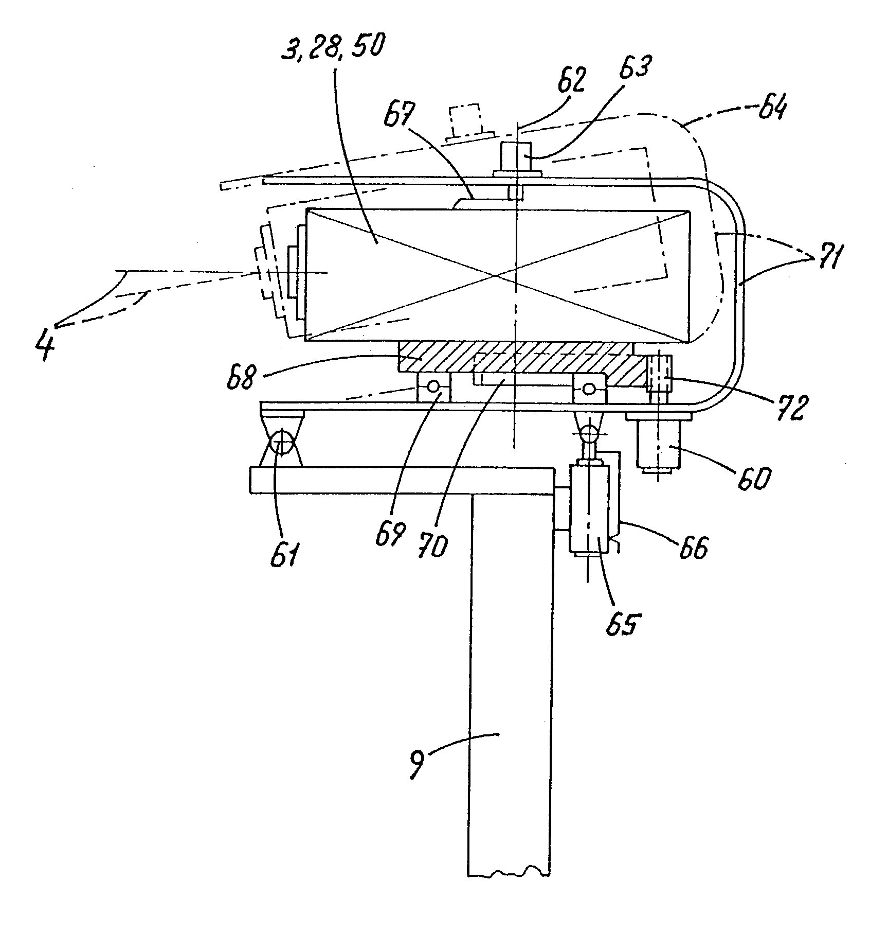
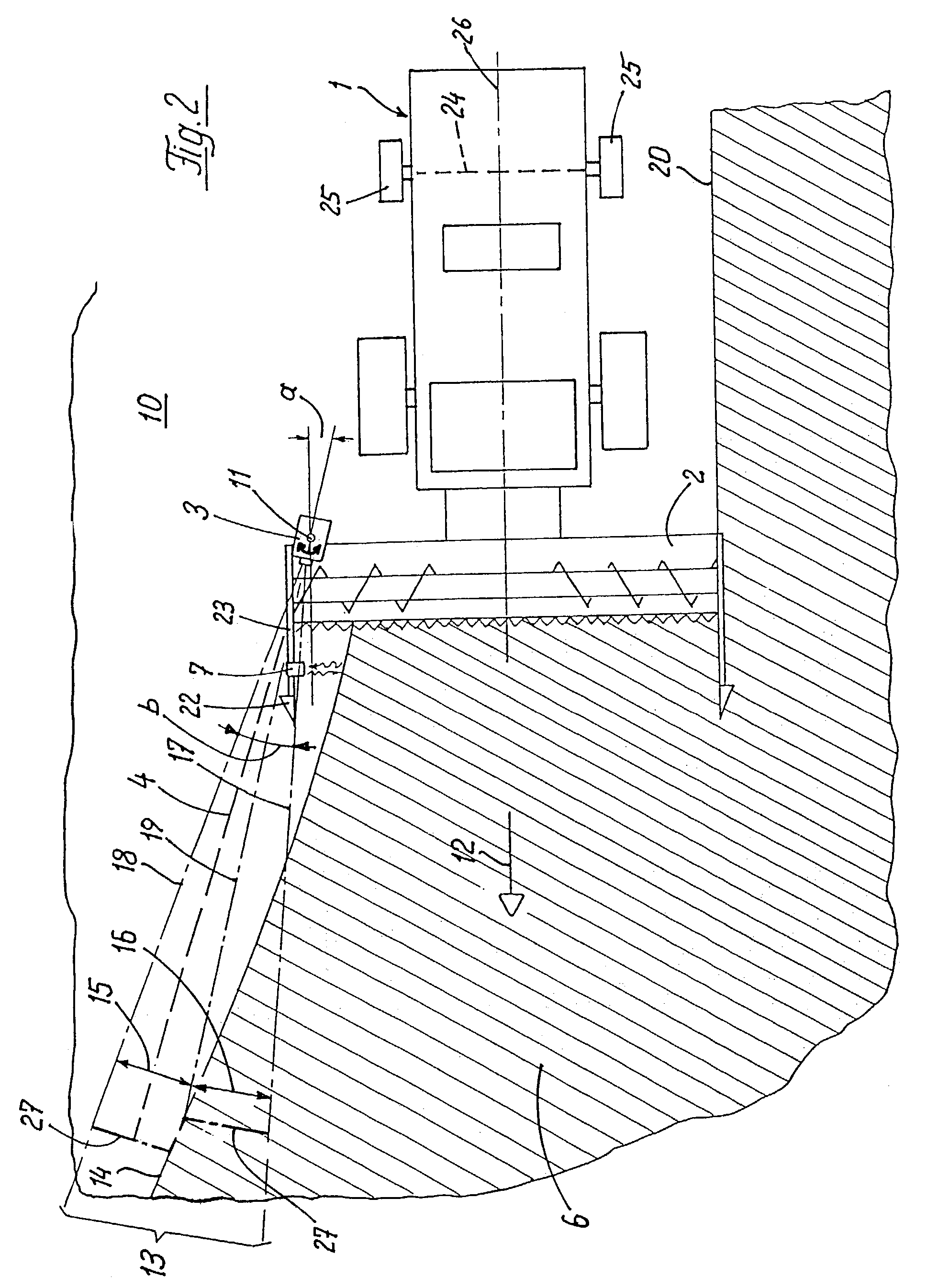
[0007]Advantageously, the position-finding device never loses the guide variable even in cases of greater variations in the path of the guide variable. The region of coverage of the position-finding device is separated from the movement of the working machine and remains oriented towards the guide variable. Further, the guide variable can be restricted to a small region. Furthermore, position-finding devices having a narrow region of coverage, such as the ultrasonic position-finding device described in the prior art, can be used. By using a narrow region of coverage, the position-finding devices yields, in connection with the proposed solution, the added advantages described below. The position-finding devices are less expensive as a result. This is achieved in particular by the possibility of using an ordinary swivel mechanism for the contactlessly operating scanning signal. Furthermore, position-finding devices of this kind can be orientated selectively towards a guide variable and are, therefore, not affected by any further guide variables existing in the area surrounding the guide variable or further existing contour changes which are detected as well. Further, there is the possibility of obtaining a higher scan rate with a comparably smaller data quantity. The reliability of detection of the guide variables is noticeably increased as a result. Advantageously, the position-finding device with a small region of coverage can first be swivelled automatically or manually over a region, by means of the adjusting device according to the present invention, for example to initialize the position-finding system or to automatically adapt to different working widths of the front attachments or implements or to find a guide variable, in order then to use the found or selected position of a guide variable relative to the working machine as the basic orientation or neutral position.
[0023]The use of a position-finding device is versatile and inexpensive when used on different agricultural working machines or used on one working machine, respectively. In a particular embodiment of the invention, the region of coverage of the position-finding device in conjunction with the guide variable to be located can be adapted to the latter. This makes it possible to detect different guide variables from a scanned contour, due to a varying scanning width depending on the guide variable. Detection of the center of a swath as the guide variable requires coverage across the whole width of the swath cross-section. A working edge, on the other hand, can be reliably detected in a smaller region of coverage. Adaptation allows a limited data quantity produced, determined as a function of the detected guide variable. A working edge or loading receptacle edge being aimed is determined by a sudden change of distance in the scanned contour. By adaptation or restriction of the scanning distance performed in certain regions, other guide variables which are adjacent but further away can be cut out and as a result reliable detection of the desired guide variable can be enabled.

Problems solved by technology

The disadvantage to this system is that the maximum possible region of coverage is limited, so that greater variations in the path of the grain edge cannot be detected by this position-finding device and stable automatic steering can no longer be ensured.
A further disadvantage arises due to the slow reaction of the agricultural machine to a steering movement.
A variation in the relative position of the grain edge to the agricultural machine which is detected by the position-finding device is directly converted to a steering movement by the automatic steering system of the agricultural machine; but because of the mass inertia of the agricultural machine, there is a delayed, slow reaction of the change of direction of travel of the agricultural machine.
Disadvantageously, the region of coverage of the position-finding device may no longer cover the grain edge, and automatic steering of the agricultural machine in a stable fashion is no longer possible.
There can, therefore, be insufficient load on a cutterbar or crop losses due to the feed region moving past the standing or lying crop.
This is a disadvantage because the large region of coverage of the laser distance measuring device requires a high scanning speed of the laser beam, which also leads to the storage of a larger quantity of data and longer time to evaluate the data.
This adversely increases the cost of the position-finding device for this remote scanning, requires a higher scan rate of the device and requires a longer time for data evaluation of the higher data quantity produced.

Method used


Image

  • Agricultural machine with a guidance system
  • Agricultural machine with a guidance system
  • Agricultural machine with a guidance system

Examples


Embodiment Construction

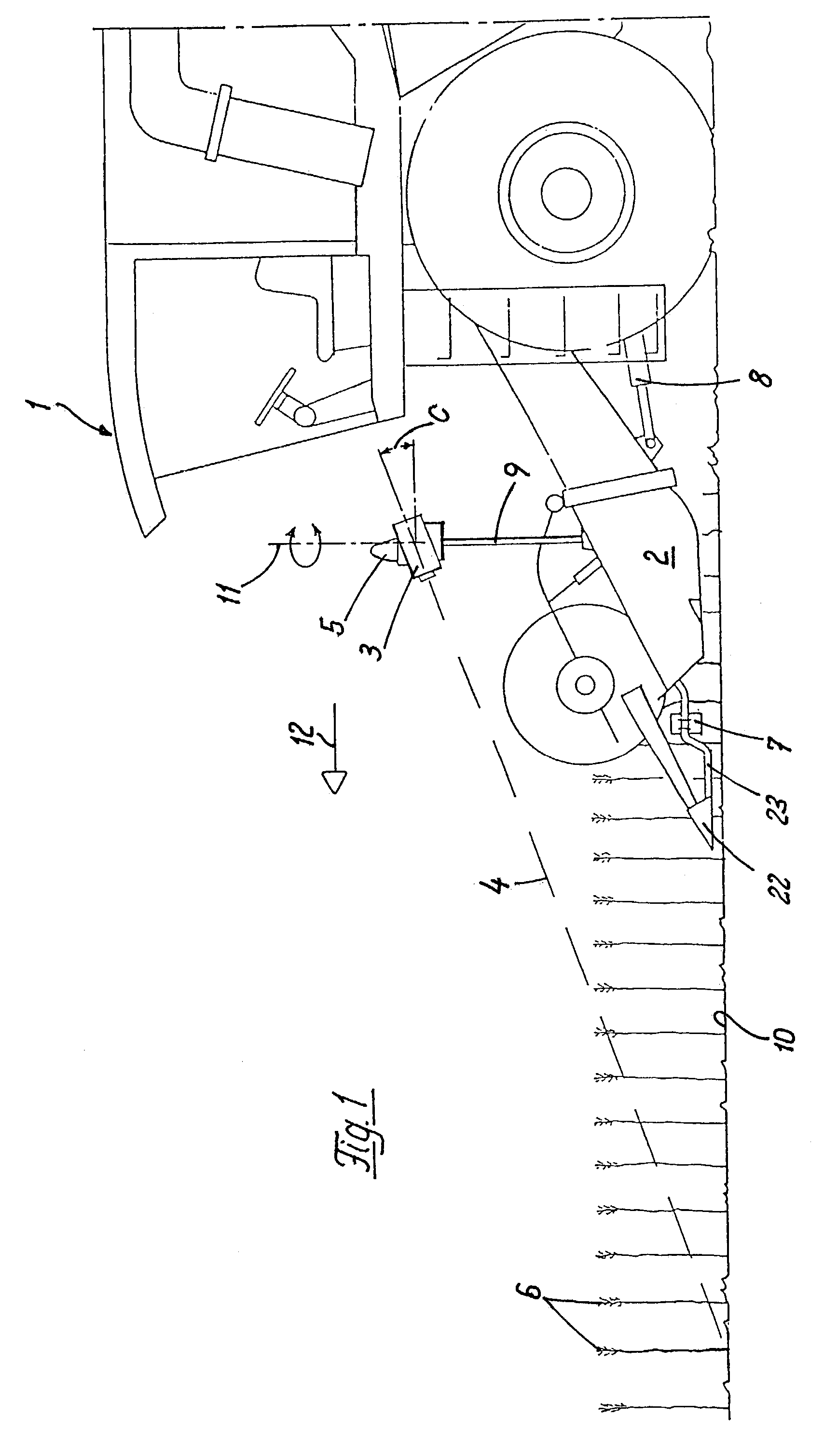
[0029]FIG. 1 shows a combine harvester 1 having a cutterbar 2 mounted thereon so as to be vertically movable and swivellable about a horizontal axis by means of a lifting cylinder 8. The combine harvester 1 has a position-finding device 3 attached thereto. The position-finding device 3 is mounted above a grain edge on a supporting tube 9 so as to be automatically swivellable about at least one vertical swivel axis 11 relative to the supporting tube 9 and the combine harvester 1, wherein this swivel angle can rotate 360°. The position-finding device 3, which is inclined at in angle c to standing crop 6 ahead in the direction of travel 12, senses by means of a scanning beam 4 the distance between the position-finding device 3 and the standing crop 6 and field 10. In particular, this distance is determined by means of interval measurement between transmitted and received radar, sound or light pulse.

[0030]In FIG. 1, a laser reflex position-finding device is shown as the position-finding...


PUM


Abstract

A self-propelled agricultural machine having a position-finding system including a position-finding device for detecting positions of guide variables relative to the machine and at least one adjusting device for adjusting the orientation of the region of coverage of the position-finding device relative to the machine. The position of the crop edge detected by the position-finding device is used for adjustment of the orientation of the region of coverage of the position-finding device relative to the machine. The position-finding system provides reliable control of the machine along the path of the crop edge. At least one adjusting device orientates the positioning-finding device relative to the machine for tracking the machine along the detected crop edge. In addition, the signals of a further position-finding device in a feed region of a cutterbar is taken into consideration.

Description

TECHNICAL FIELD OF THE INVENTION[0001]The invention relates generally to a self-propelled agricultural machine, and more specifically, a self-propelled agricultural machine having a contactlessly operating position-finding device and an adjusting device for adjusting the orientation of the position-finding device relative to the working machine.DESCRIPTION OF THE RELATED ART[0002]Self-propelled agricultural working machines having position-finding devices for relieving the pressure on the operators of the machines and for increasing the machine capacity in the working mode. This is achieved by the determination of a relative position of a transport vehicle, a working edge or guide variable in relation to the working vehicle and the systems for control or regulation of adjusting parameters or automatic tracking system which are dependent thereon. There are a few contactlessly operating position-finding devices known in the art. DE 195 08 942 A1 describes an agricultural machine havin...

Claims


Application Information

Patent Timeline
IPC IPC(8): A01D41/14A01D41/127A01D46/08
CPCA01D43/073A01D41/1278G05D1/024
Inventor DIEKHANS, NORBERT
Owner CLAAS SELBSTFAHRENDE ERNTEMASCHINEN GMBH
Learn More