Dual, coupled check valve for direct drive, reversible power sources for hydraulic systems

a technology of hydraulic system and check valve, which is applied in the direction of fluid couplings, couplings, wing accessories, etc., can solve the problems of excessive liquid volume, excessive discharge, and typical electrical failure of solenoid valves, and achieve the effect of minimizing liquid flow resistance and high spring constan

Active Publication Date: 2007-01-02
LAST HARRY J
View PDF7 Cites 33 Cited by
  • Summary
  • Abstract
  • Description
  • Claims
  • Application Information

AI Technical Summary

Benefits of technology

[0023]A particular aspect of the invented dual, coupled check valve mechanism is that the circumferential cross section configuration of the translating rod is not necessarily circular but rather may be rectangular, or a helical annulus with a very high spring constant or other shape that tends to minimizes liquid flow resistance of the hydraulic liquid flowing in the volume region around the translating rod in the translation passage to the mid-passageway drain to the reservoir.
[0024]Another novel feature of the invented dual, coupled check valve is that a combination of a single pressure relief valve / pressure (interrupt) switch hydraulically coupled to a plenum of a common pressure shuttle valve, respectively coupled hydraulically between the plenums at each end of the translation passageway of the manifold can protect the involved hydraulic circuit from over / under pressurization.

Problems solved by technology

While these invented systems perform quite satisfactorily using conventional remote reversible hydraulic power packs and / or remote unidirectional hydraulic pump in a combination where a solenoid valve is utilized for reversing the direction of liquid flow to the dual motor drive system, excess discharge problems arise when simpler direct drive, reversible hydraulic power packs / pumps are chosen as the source of hydraulic power.
The disadvantage of such systems is the necessity for the three position solenoid valve which directs hydraulic flow in a first direction in the particular hydraulic at position one, recycles hydraulic liquid to the pump input port at position two, and directs hydraulic flow in a opposite direction in the particular hydraulic at position three.
Such solenoid valves typically electrically fail due to wear and environmental conditions.
Similar excess liquid volume problems are encountered when a direct drive, reversible hydraulic gear-type power source is incorporated into a combination of drive coupled, anal hydraulic reversible hydraulic motors with mechanically coupled drives for driving winding systems translating a structure such as a swimming pool cover back and forth across a swimming pool.
In such winding systems, initially the liquid volume output from the driving motor typically exceeds the input volume requirements of the driven (pumping) motor, which if not alleviated causes the driven motor to rotate at a faster rate possibly overdriving, and unwinding of the component coupled to its drive shaft allowing slack to develop between the translating mechanical components coupling to the respective mechanical drive shafts of the coupled hydraulic motors.
An external force can also cause over rotation of the particular driving motor moving the translating components coupling between the respective mechanical drives of the dual reversible hydraulic motors to an undesired position particularly since, in static circumstances the anti-cavitation manifold allows drive shaft of the last driven (pumping) motor to rotate in either the ‘driving’ or ‘pumping’ direction responsive to an external force.
The disadvantages of the Oildyne shuttle cock or spool value, relate to the fact that the entire flow in the particular discharge leg of circuit is directed into reservoir requiring the direct drive, reversible motor to make up or pump hydraulic all liquid requirements for driving the circuit from the reservoir via check valves 8 or 9 which must be present for proper functioning of any involved hydraulic circuit.

Method used


Image

  • Dual, coupled check valve for direct drive, reversible power sources for hydraulic systems
  • Dual, coupled check valve for direct drive, reversible power sources for hydraulic systems
  • Dual, coupled check valve for direct drive, reversible power sources for hydraulic systems

Examples


Embodiment Construction

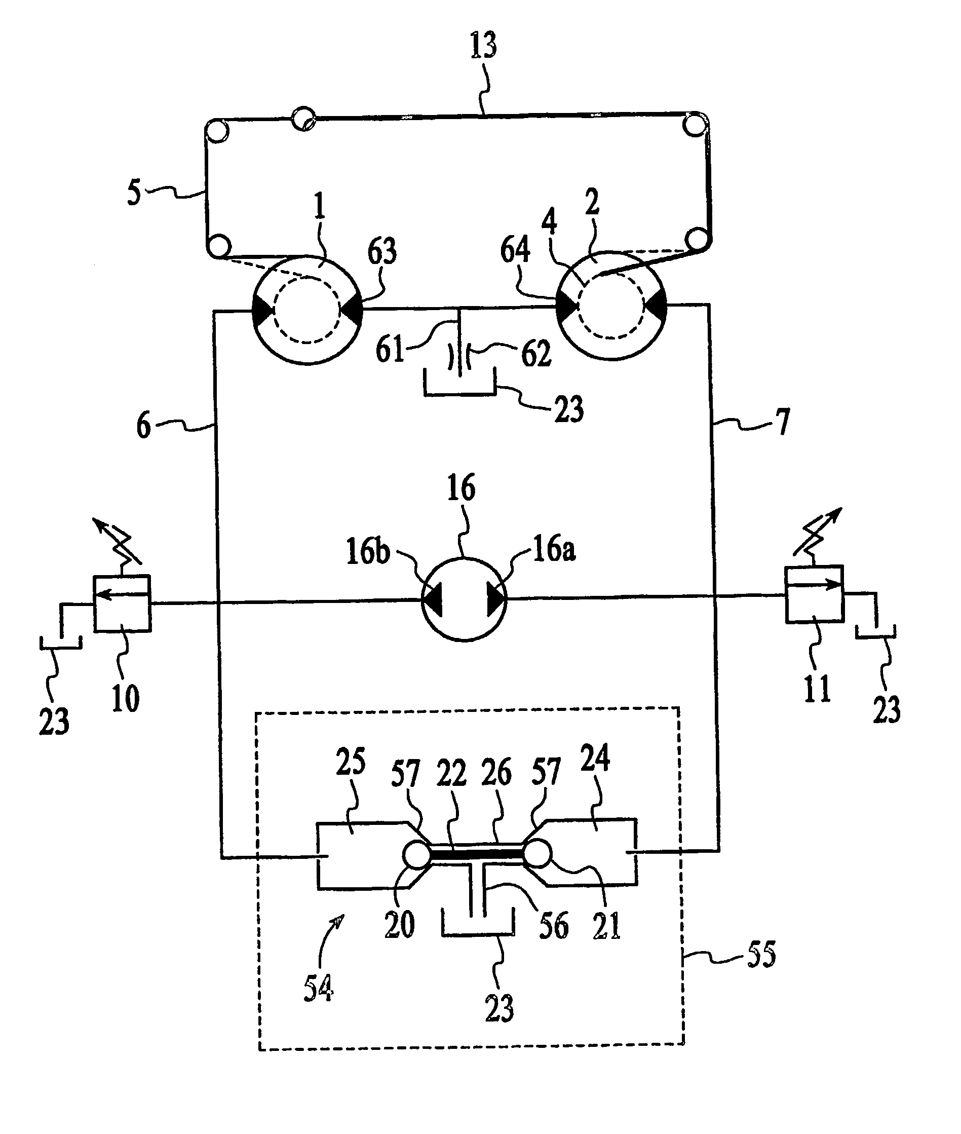
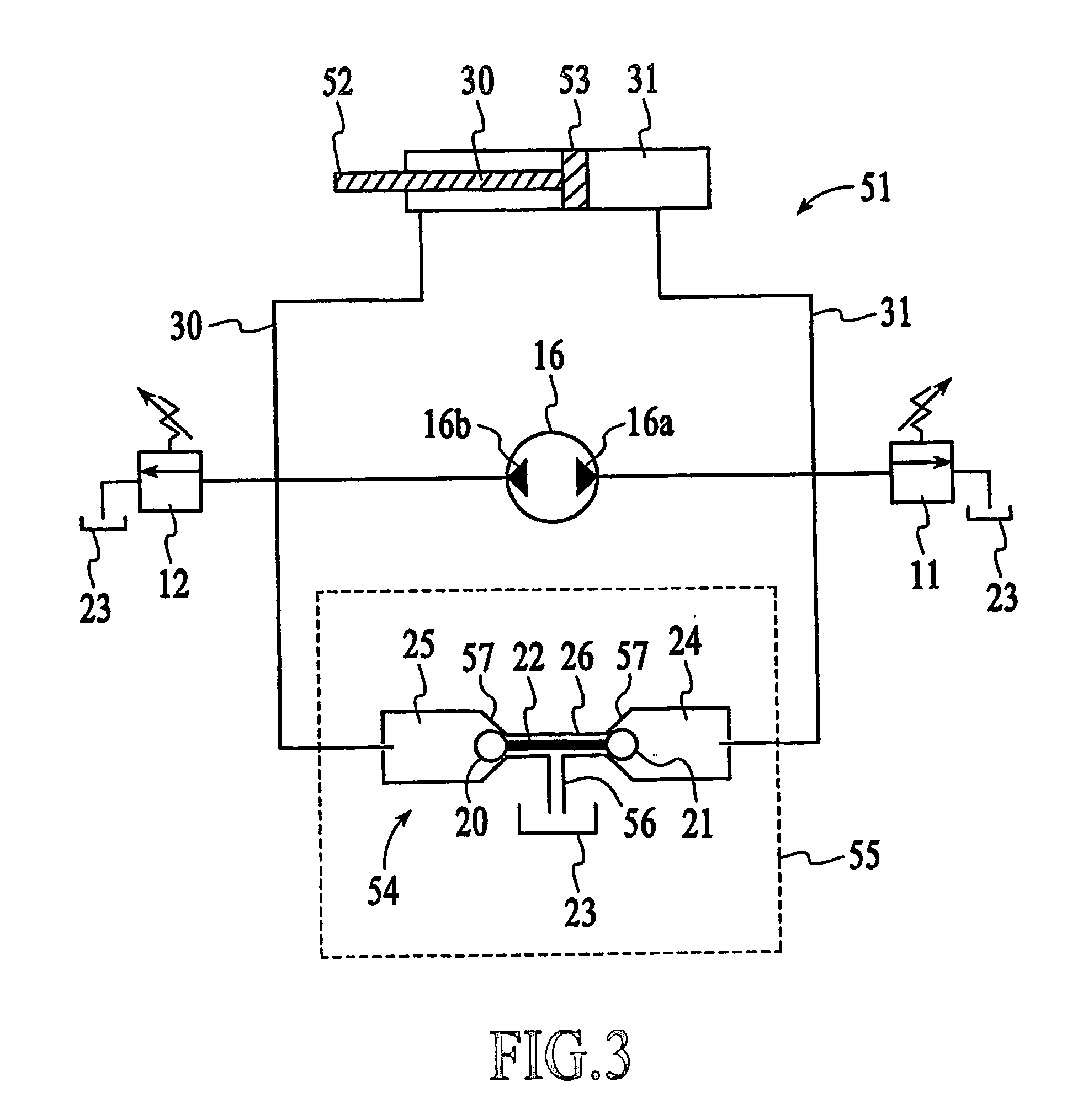
[0030]Referring to FIG. 3, the schematic illustrates a hydraulic circuit 51 that incorporates a direct drive, reversible hydraulic pump 16 supplying power for extending and retracting a typical hydraulic rod 52 extending from a piston 53 within a hydraulic cylinder HC in combination with the invented dual, coupled check valve indicated generally at 54 hydraulically coupled to the reservoir 23 for the hydraulic circuit 11. As illustrated the hydraulic circuit includes pressure relief valves 11&12 monitoring and relieving over-pressurization (excess volume) in both the rod leg 30 and blind side leg 31 of the hydraulic circuit 51.

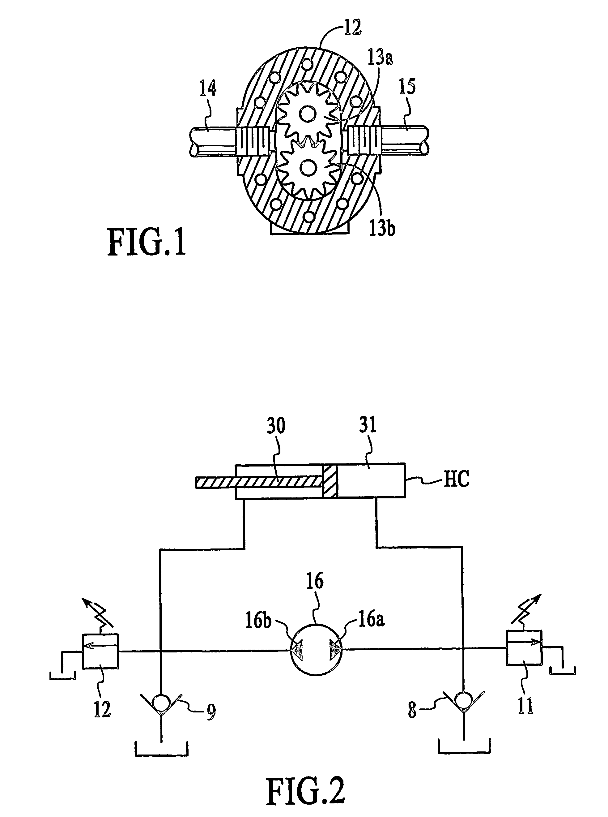
[0031]Comparing the prior art circuit (FIG. 2), the skilled hydraulic circuit designer will note the that check valves 8&9 shown in the prior art circuit have been replaced with the invented dual, coupled check valve 54 which includes a manifold indicated by dashed line 55 defining a translation passageway 26 having a mid-passage drain 56 hydraulically communi...


PUM


Abstract

An invented dual, coupled check valve mechanism is described for a direct drive, reversible hydraulic power source for hydraulic circuits that includes a manifold hydraulically coupled to the respective input / output ports and a reservoir of the hydraulic power source defining a translation passageway having mid-passage drain hydraulically coupled to the reservoir, where each end of the translation passageway has an angled annular valve seat opening to larger diameter plenum containing a check valve ball. A translating rod with a length greater and a circumferential diameter less than that of the translation passageway located in the translation passageway prevents the respective check valve balls from simultaneously seating on the valve seats at the respective ends of the translation passage way.

Description

RELATED APPLICATIONS[0001]This Application relates to U.S. Provisional Patent Application Ser. No. 60 / 455,999 filed Mar. 18, 2003 entitled FLOW CONTROL APPARATUS FOR USE WITH FLOW DIRECTION REVERSING PUMPS IN A HYDRAULIC SYSTEM, which is incorporated herein by reference in its entirety, and claims any and all benefits to which it is entitled thereby.BACKGROUND OF THE INVENTION[0002]1. Field of the Invention[0003]The invention relates to an inherent control mechanism for direct drive reversible hydraulic pumps supplying power to hydraulic circuits performing work, and in particular, a dual, coupled check valve for eliminating the necessity for pressure relief valves for resolving excess flow in a discharge leg of any hydraulic circuit such as coupled dual motor, reversible hydraulic drive systems, powered by a direct drive, reversible hydraulic power source.[0004]2. Description of the Prior Art[0005]In U.S. Pat. Nos. 5,184,357, 5,327,590, and 5,546,751 Applicant, Harry J. Last descri...

Claims


Application Information

Patent Timeline
Patent Type & Authority Patents(United States)
IPC IPC(8): F16D31/02E04H4/10F15B7/00F15B7/10
CPCF15B7/006F15B7/008F15B7/02F15B7/10E05F15/56F15B2211/613F15B2211/7053F15B2211/7058F15B2211/20561
Inventor LAST, HARRY J.
Owner LAST HARRY J
Why Eureka
Try Eureka