Radiation dosimeter device

a technology of radiation dosimeter and dosimeter, which is applied in the direction of x/gamma/cosmic radiation measurement, radio control devices, instruments, etc., can solve the problems of significant spacecraft resources being disadvantageously required, the dosimeter weighs several pounds, and the microelectronics of spacecraft are vulnerable to degradation and even failure, so as to improve the measurement of radiation exposure and improve the effect of radiation exposure measuremen

Active Publication Date: 2007-01-02
THE AEROSPACE CORPORATION
View PDF6 Cites 23 Cited by
  • Summary
  • Abstract
  • Description
  • Claims
  • Application Information

AI Technical Summary

Benefits of technology

[0012]Another object of the invention is to provide a radiation dosimeter device for the detection of accumulated radiation from charge deposits above a threshold and including prethreshold radiation detection charge accumulations for improved measurement of radiation exposure.
[0013]Yet another object of the invention is to provide a radiation dosimeter device for the detection of accumulated radiation from charge deposits above a threshold and including prethreshold radiation detection charge accumulations for improved measurement of radiation exposure and generates an analog signal representing the amount of radiation exposure.

Problems solved by technology

Microelectronics in spacecraft are vulnerable to degradation and even failure from the radiation dose caused by energetic electrons and ions.
However these dosimeters weigh several pounds, consume several watts, and must be mounted on the surface of the spacecraft with a clear 2π view of space.
Thus, significant spacecraft resources are disadvantageously required.
Annealing effects, among others, make interpretation difficult.
There are several problems associated with the Type 1 dosimeter.
This detailed process is prone to error from tolerance build-up in the analysis and from inherent errors in transforming what are typically very complex spacecraft geometries into a simple single thickness of metal.
Furthermore, even minor changes in the vehicle design can cause a significant error unless a new ray-tracing analysis is performed.
The second problem with the Type 1 dosimeter is the necessary mounting on the spacecraft that requires that each sensor have a clear field-of-view.
This constraint puts the dosimeter payload in competition for precious real estate on the spacecraft or requires that the dosimeter settle for some non-ideal spacecraft obstruction to the field-of-view.
Finally, radiation transfer calculations are complex and require highly accurate models of the spacecraft of interest in order to obtain accurate results.
These calculations are far from trivial or cheap to carry out.
The main problem with this degradation dosimeter technique is that it is indirect, in that, the devices do not measure radiation dose but the radiation effects upon a specific device.
Not all devices degrade in the same way or at the same rate and the understanding of rate and annealing effects become critical.
These indirect radiation effects make the interpretation of the device output prone to serious error.
However, one cannot expose devices to the full range of dose when those same devices are to be positioned in orbit.
So, flight devices are typically irradiated at unrealistically low doses on the ground with an extrapolation to predict higher doses actually occurring in orbit.
A problem with this threshold triggering is that prethreshold charge is not accumulated and represents an error in measurement either by failing to capture the prethreshold charge or by an approximation of the prethreshold triggering energy that is subject to inaccuracies.

Method used


Image

  • Radiation dosimeter device
  • Radiation dosimeter device
  • Radiation dosimeter device

Examples


Embodiment Construction

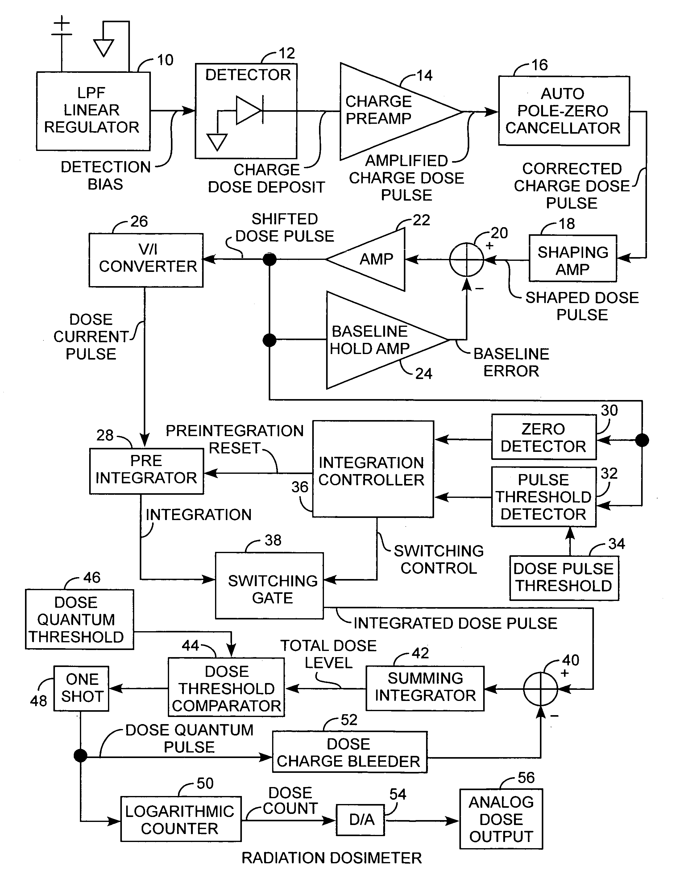
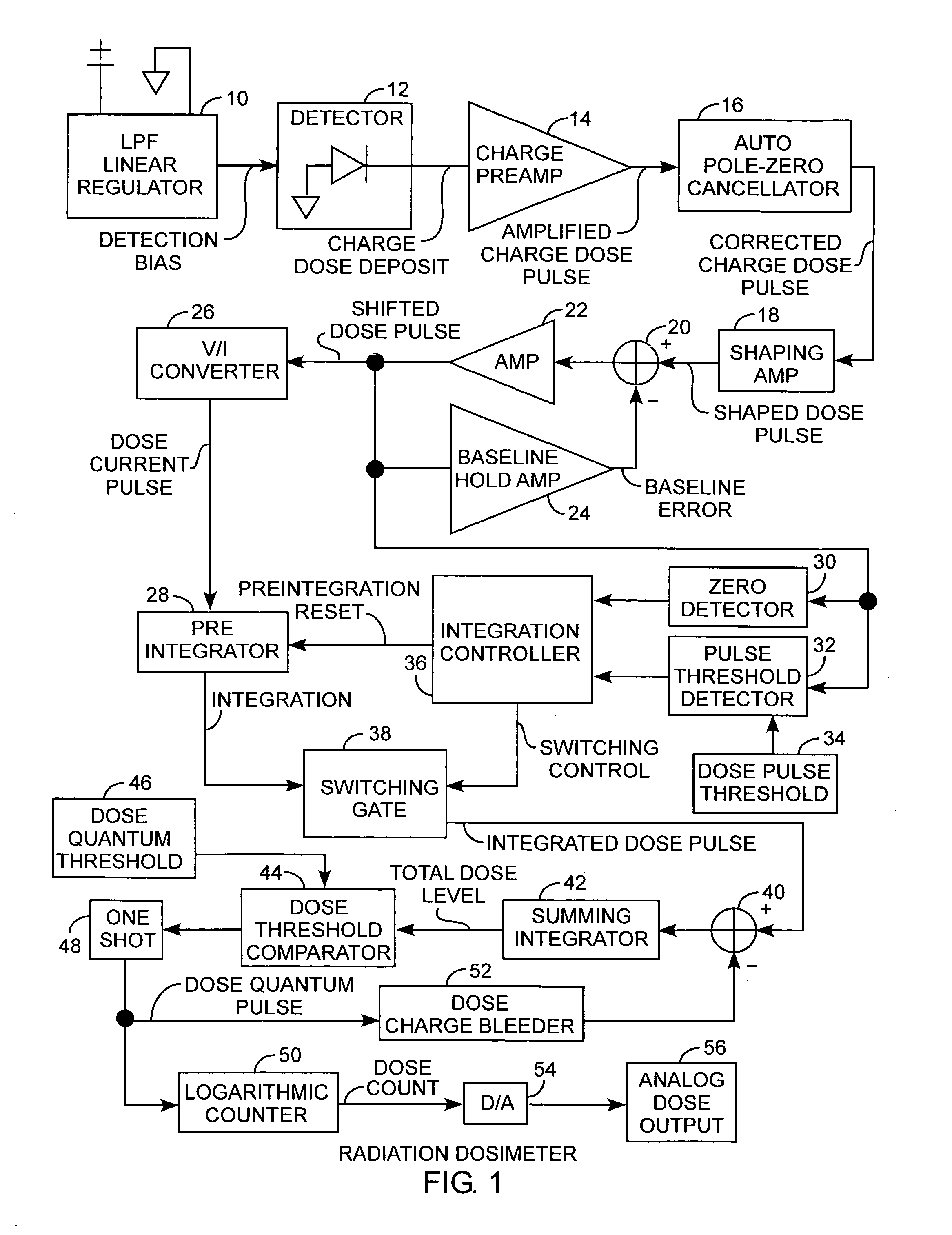
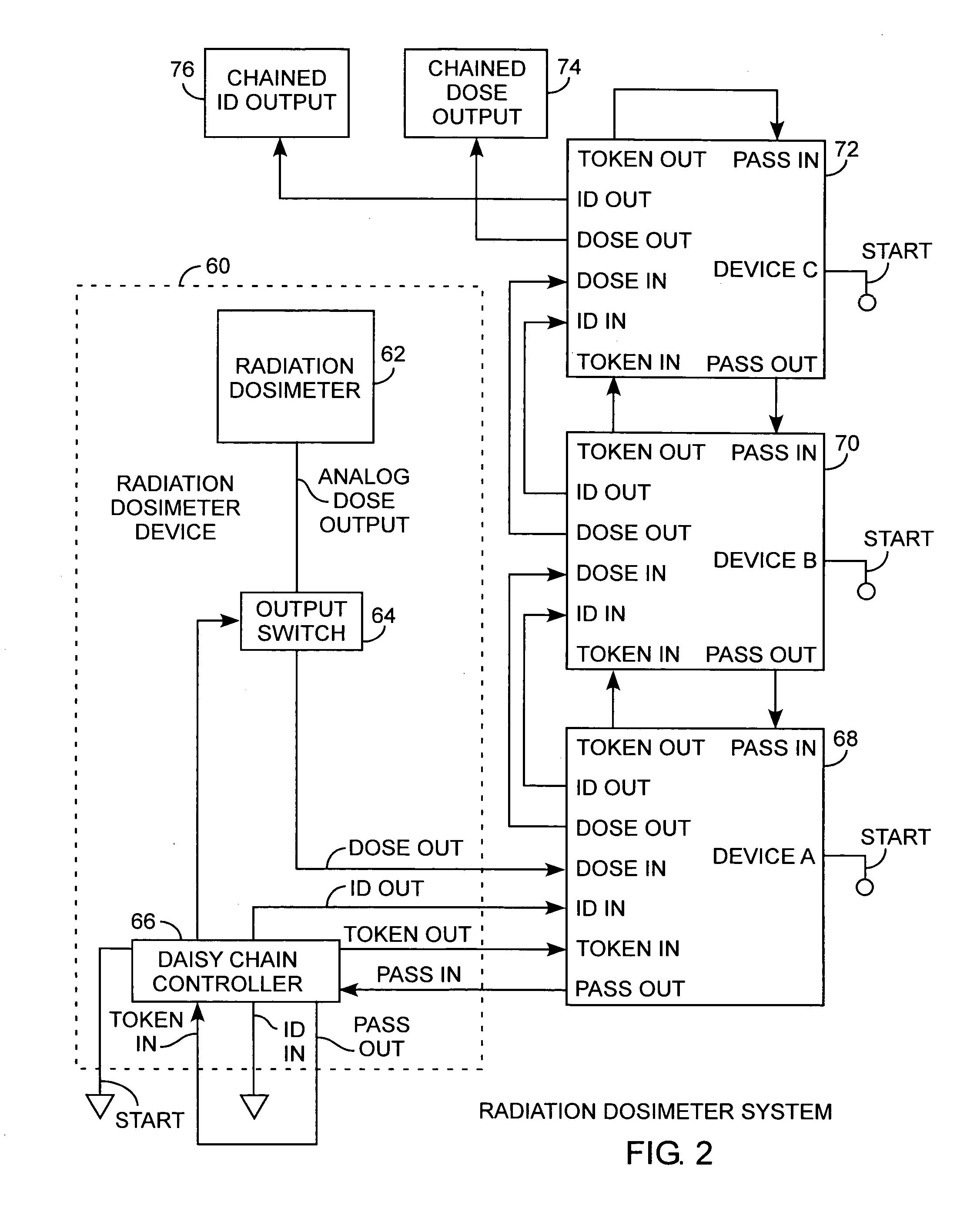
[0025]An embodiment of the invention is described with reference to the figures using reference designations as shown in the figures. Referring to FIG. 1, a radiation dosimeter, referred to herein as the dosimeter, including a low pass filter regulator 10 receiving system power. The regulator provides a detection bias for a detector 12 providing a charge dose deposit signal to a charge preamplifier 14 that in turn, provides an amplified charge dose pulse to an auto pole-zero cancellator 16. The charge dose pulse represents a pulse of received radiation by the detector 12. The cancellator 16 provides a corrected charge dose pulse to a shaping amplifier 18 for providing a shaped dose pulse to a pulse summer 20. Each shaped dose pulse represents a defined pulse for accumulation of shaped dose pulses for accumulating total charge. The summer provides a corrected pulse to a pulse amplifier 22 that in turn provides a shifted dose pulse to a baseline hold amplifier 24 and a voltage to curr...


PUM


Abstract

An improved radiation dosimeter device in an improved radiation dosimeter system provides a DC analog output voltage that is proportional to the total ionizing dose accumulated as a function of time at the location of the dosimeter in a host spacecraft, so as to operate in a system bus voltage range common to spacecraft systems with the output being compatible with conventional spacecraft analog inputs, while the total dose is measured precisely by continually monitoring the energy deposited in a silicon test mass accumulating charge including charge contribution prior to radiation threshold detection for improved measurement of the total accumulated charge with the dosimeters being daisy-chained and distributed about the spacecraft for providing a spacecraft dose profile about the spacecraft using the improved radiation dosimeter system.

Description

REFERENCE TO RELATED APPLICATION[0001]The present application is related to applicant's copending application entitled Radiation Dosimeter System, Ser No. 11 / 342,998, filed Jan. 30, 2006, by the same inventors.FIELD OF THE INVENTION[0002]The invention relates to the field of radiation dosimeters. More particularly, the present invention relates to radiation dosimeter devices and systems for measuring radiation exposure on spacecraft.BACKGROUND OF THE INVENTION[0003]Microelectronics in spacecraft are vulnerable to degradation and even failure from the radiation dose caused by energetic electrons and ions. It is highly desirable to have radiation sensors onboard the spacecraft to serve as continuous monitors of the radiation exposure. Dosimeters can monitor radiation exposure and should be small devices that can be colocated with the critical electronic systems and economical enough in dollars and spacecraft resources to be routinely included as part of most spacecraft subsystems. A r...

Claims


Application Information

Patent Timeline
Patent Type & Authority Patents(United States)
IPC IPC(8): G01T1/02
CPCG01T1/17G01T1/026
Inventor CRAIN, JR., WILLIAM R.MABRY, DAN J.BLAKE, JOHN BERNARDKATZ, NORMAN
Owner THE AEROSPACE CORPORATION
Why Eureka
Try Eureka