
Systems and methods for implementing shader-driven compilation of rendering assets

a compilation method and shader technology, applied in the field of rendering systems, can solve the problems of high cost, no one has yet exploited the knowledge of shaders to systematically optimize rendering, and different from today's consumer level hardware, and achieve the effects of fast iteration of art assets, rapid and flexible execution, and dramatic simplified runtime apis

Active Publication Date: 2007-01-02
ELECTRONICS ARTS INC
View PDF4 Cites 52 Cited by
  • Summary
  • Abstract
  • Description
  • Claims
  • Application Information

AI Technical Summary

Benefits of technology

[0023]to efficiently render fixed topology objects with fixed shading effects;
[0027]The present invention provides a real-time rendering system comprised of a small, efficient runtime engine with a portable API, and a modular retargetable art asset compiler. The runtime engine is implemented both on top of existing graphics APIs and at the driver level. An art asset is authored in some geometric modeling package, such as Alias|Wavefront Maya, 3D Studio Max, or SoftImage XSI. The asset preferably includes the geometry, the per-vertex attributes, and a collection of materials (surface properties, colors, texture map usages, etc.) and textures for the asset. The asset description is sufficiently rich that the object can be rendered as it should appear on final use without programmer intervention.
[0029]In one embodiment of the present invention, the binding of geometry to the shader is explicitly managed in the art asset compiler. This provides many benefits. For example, user code specific to a particular asset is only required if there are explicit exposed runtime shader parameters. Additionally, as a corollary to the above, an artist can quickly iterate an art asset on the target platform without programmer intervention. Moreover, the runtime API is dramatically simplified, since all geometry specification and binding is preferably performed off line.
[0030]In one embodiment, rendering objects are constructed off-line, and parameterization of these objects is addressed through runtime linkage of external variables to the rendering objects and by exporting various parts of the objects to the runtime for modification. These methods allow aggressive optimization around parameterized elements of the models of the present invention.
[0031]The resulting system is fast and flexible. It has shown itself to be as fast or faster than existing custom rendering engines. Porting the system of the present invention to a new platform is significantly faster than porting a custom game engine and tool suite to new hardware.

Problems solved by technology

Programmers often attempt to generalize this code to deal with multiple assets, at the expense of efficiency.
Although shader compilers have been explored as a partial solution to this problem, no one has yet exploited knowledge of the shader to systematically optimize rendering.
PixelFlow is inherently well suited to programmable shading, but is very different from today's consumer level hardware.
These programs are more complex than they might appear at first glance, since they require both runtime code to manage the bindings, as well as synchronized tool code to generate the appropriate data for the runtime.
However, the raw output models are rarely suited to consumer level hardware.
The first versions of OpenGL were similarly limited, leading to high function call overhead on polygon submissions.
Although vertex arrays speed submission of geometry data, the various state setting functions in OpenGL and DirectX 8 still require considerable overhead.
Although these display lists have the potential for considerable optimization at the driver level, their construction at runtime, with the ensuing performance limitations, limits the degree to which display list optimization can be taken.
In particular, parameterized display lists are problematic.
This architecture does not, however, allow the driver to optimize state changes across such a nested display list call, as the newly defined list may affect any of the state that had been set in the parent display list.

Method used


Image

  • Systems and methods for implementing shader-driven compilation of rendering assets
  • Systems and methods for implementing shader-driven compilation of rendering assets
  • Systems and methods for implementing shader-driven compilation of rendering assets

Examples


Embodiment Construction

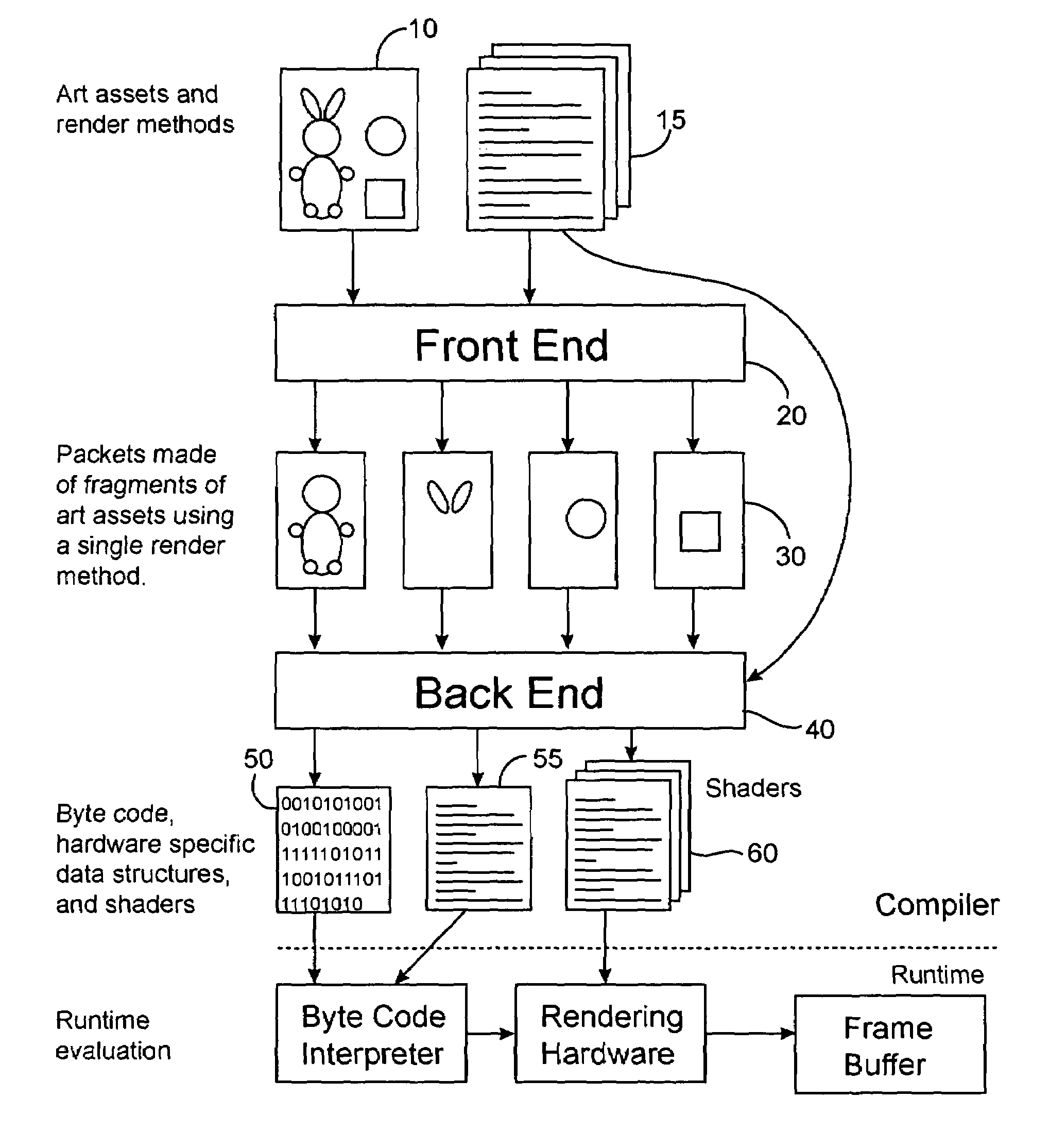
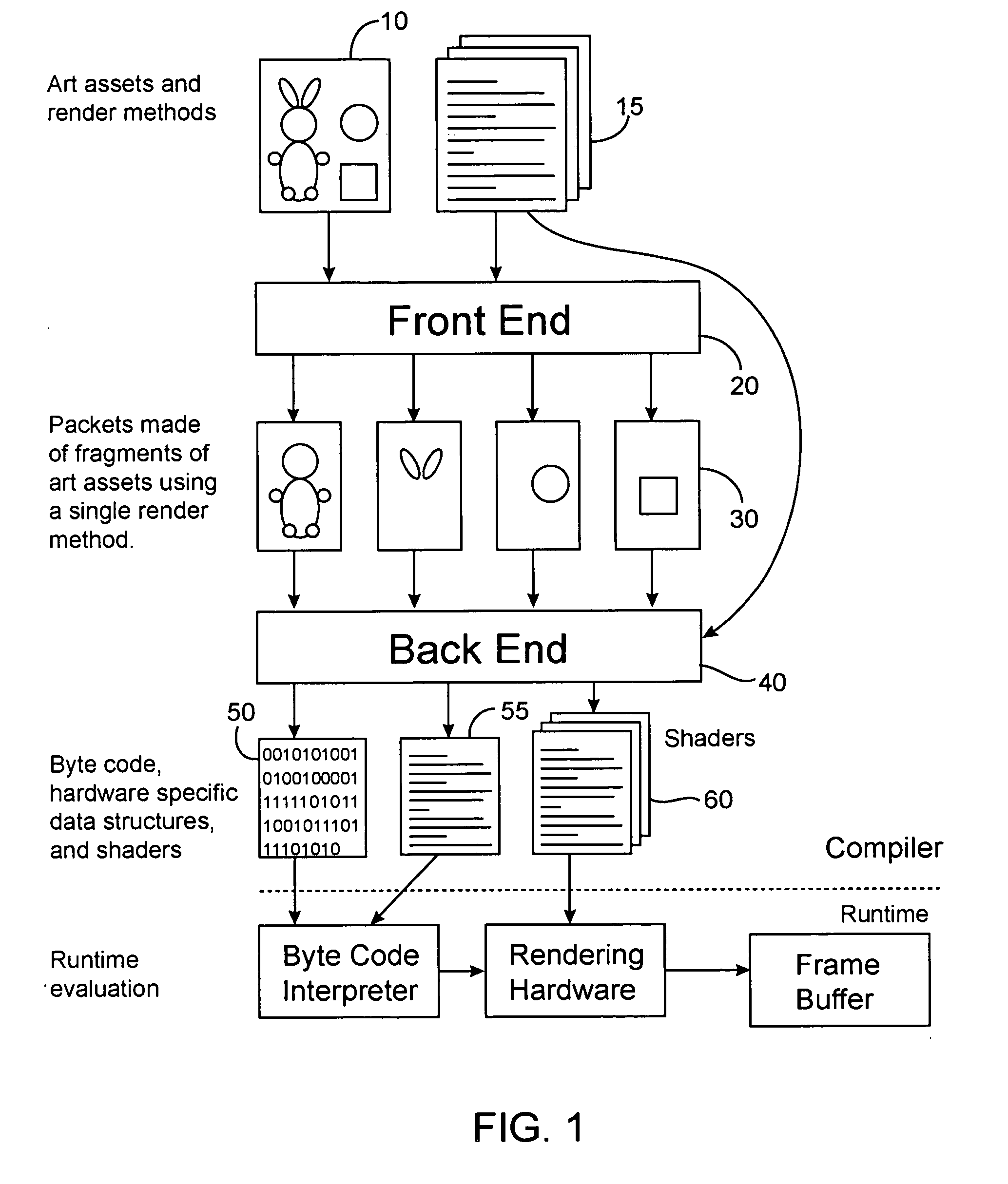
[0040]One embodiment of a system of the present invention is illustrated in FIG. 1. As shown, an art asset 10 and an extension of shader specifications, called the render methods, 15 which include a declaration of shader input variables and off-line computations to generate these variables from the art asset, are provided to the front end 20 of an art asset compiler. The compiler front end 20 takes as input the art asset 10 and render methods 15, e.g., polygonal geometric data and model attributes, and produces segmented, geometrically optimized asset fragments, called packets, 30 representing individual calls to the render methods. It should be appreciated that alternative front ends can be constructed to address non-polygonal data, such as spline surfaces or particle systems using the teachings of the present invention. A back end 40 of the asset compiler takes packets 30 generated by the front end, and generates optimized code and data streams 50, hardware specific data structure...


PUM


Abstract

Art asset rendering systems and methods in which pre-processing is performed in a compilation process. Geometric data are processed in the compilation process with knowledge of associated shading programs. The data are converted into data structures targeted directly to a target hardware platform, and a code stream is assembled that describes the manipulations required to render these data structures. The compiler includes a front end configured to read the geometric data and attributes (an art asset) output from a 3D modeling package and shaders in a platform independent form and perform platform-independent optimizations, and a back end configured to perform platform-specific optimizations and generate platform-targeted data structures and code streams.

Description

CROSS-REFERENCES TO RELATED APPLICATIONS[0001]The present application claims the benefit of U.S. Provisional Application Ser. No. 60 / 363,049, filed Mar. 8, 2002, the contents of which are hereby incorporated in its entirety for all purposes.BACKGROUND OF THE INVENTION[0002]The present invention relates generally to rendering systems and more particularly to art asset rendering based on shader-driven compilation methods.[0003]In consumer applications such as video games the topology of most graphical elements is fixed, unlike the case of modeling applications, such as Alias|Wavefront Maya™, SoftImage XSI™, and 3D Studio Max™. Hardware designers, both of game consoles and of graphics accelerator chipsets, have exploited this and have designed their hardware to be most efficient at rendering large constant sets of geometry than at rendering individual polygons. This is reflected in the typical APIs used: both Microsoft's DirectX 8 and OpenGL 1.1 and later versions (e.g., OpenGL:1999), ...

Claims


Application Information

Patent Timeline
IPC IPC(8): G06F9/45G06F9/44G06T15/00
CPCG06T15/00
Inventor SCHENK, ERICLALONDE, PAUL
Owner ELECTRONICS ARTS INC
Learn More