Twist-lock terminal connection system

a terminal connection and twist lock technology, applied in the field of high current terminals, can solve the problems of electrical arcing, loss of contact, other undesirable events, etc., and achieve the effects of reducing labor, increasing electrical contact surface area, and reducing labor costs

Inactive Publication Date: 2007-01-09
YAZAKI NORTH AMERICA
View PDF8 Cites 28 Cited by
  • Summary
  • Abstract
  • Description
  • Claims
  • Application Information

AI Technical Summary

Benefits of technology

[0015]The invention enables a reduction in labor needed during vehicle assembly of the harness and PDM terminals and elimination of some assembly tools such as wrenches or pneumatic drivers. No tools are required to directly assemble or mate the terminals. The required contact force is provided, and there is increased electrical contact surface area for higher reliability. One half of the interface is stamped as part of the bus bar, adding little or no

Problems solved by technology

The use of tools provides opportunities for cross-threading or improperly torqued attachments that could cause loose connections.
In

Method used


Image

  • Twist-lock terminal connection system
  • Twist-lock terminal connection system
  • Twist-lock terminal connection system

Examples


Embodiment Construction

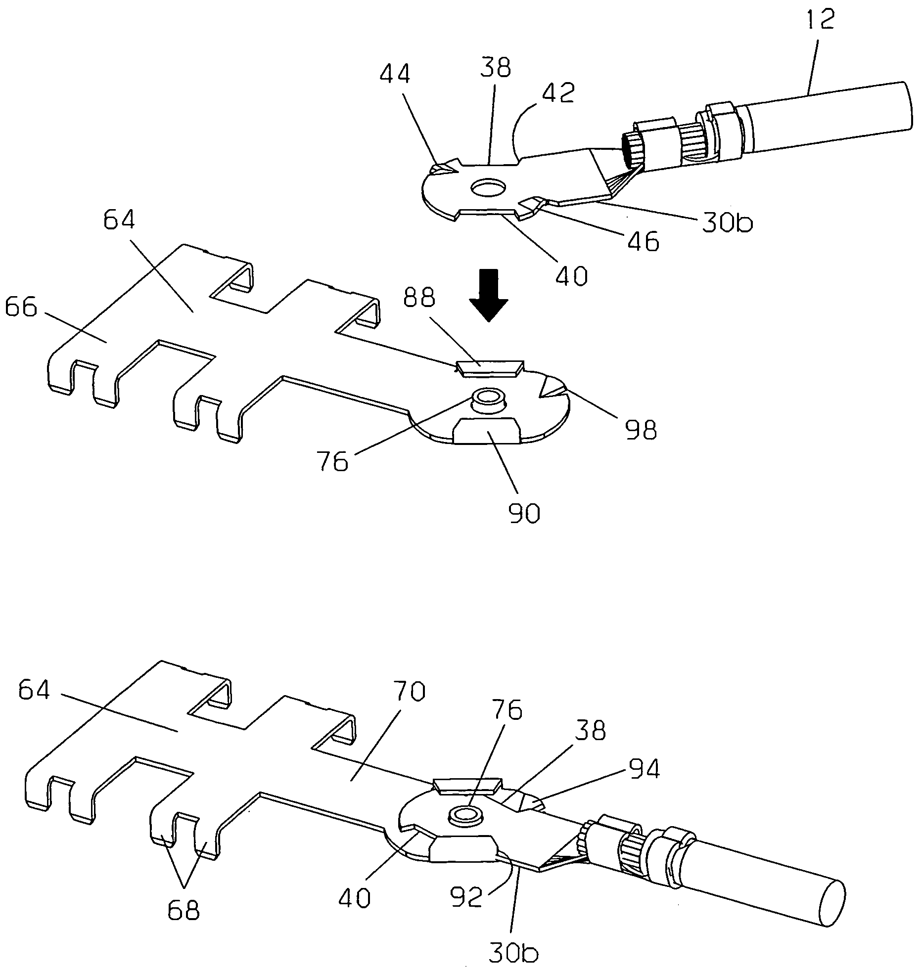
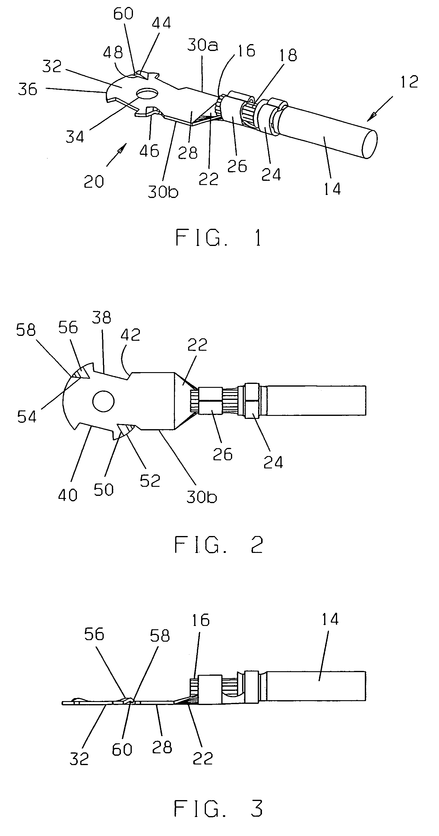
[0027]Referring now to FIGS. 1–3, a first or harness-side terminal of an electrical connection system, for attachment to a high power cable or wire harness 12, is illustrated. The harness has an insulative jacket 14 surrounding a conductor or conductors 16. The conductors 16 are exposed at an end 18 of the harness. A harness-side terminal 20 has a first, wire-connect section 22 including two sets of tabs. An outer set of tabs 24 is for crimping around the insulative jacket 14 of the cable or harness 12 to secure the terminal and harness together. An inner set of tabs 26 is for crimping around the exposed conductor 16 of the cable to make electrical contact between the wire and terminal. A relatively flat, straight second or stem section 28 of the terminal integrally extends from the wire-connect section. The stem section has two parallel, opposite sides 30a and 30b and makes an integral junction with a third, mating section 32.

[0028]The third or mating section 32 of the harness-side...


PUM


Abstract

An electrical terminal connection system includes first and second terminals that are interlocked by placing the first terminal on top of the second terminal and rotating the first terminal. The first terminal has a planar ring section with an outer perimeter and a centrally located aperture. The perimeter has cut-out portions. Inclined spring elements extend from the ring section near the outer perimeter. The second terminal includes a semi-circular part with an outer periphery and a centrally located collar. Curved walls extend perpendicularly from the outer periphery. The walls have ledges projecting over the semi-circular part. Aligning the cut-out portions of the first terminal with the curved walls and ledges of the second terminal enables the planar ring section of the first terminal to be placed on the semi-circular part of the second terminal, with the aperture receiving the collar. Rotating or twisting the first terminal causes the spring elements to contact and slide under the ledges. Simultaneously, a catch extending from the second terminal moves behind a locking edge formed in one of the cut-out portions of the first terminal as a side of the first terminal abuts against one of the curved walls. This prevents further rotation in either direction, maintaining the spring elements in physical and electrical contact with the ledges and interlocking the terminals. Depressing the catch enables reverse rotation and separation of the terminals.

Description

BACKGROUND OF THE INVENTION[0001]1. Field of the Invention[0002]This invention relates in general to electrical terminals and more particularly to high current terminals that are engaged and then rotated relative to each other to interlock and complete an electrical connection.[0003]2. Discussion of Related Art[0004]A power distribution center or module (PDM) is commonly used in automotive vehicles to simplify and organize electrical system wiring. The PDM consolidates relays, fuses, branch circuits, connectors and other electrical components in a single location and eliminates multi-branch wiring. The typical PDM incorporates a bus bar or similar conductor into a housing. The housing often includes a surface having a plurality of receptacles for receiving the electrical connectors, fuses, relays and other circuit components. A PDM cover usually fits over the surface and insulates and protects the components. The bus bar is routed beneath the surface and has a plurality of blade-lik...

Claims


Application Information

Patent Timeline
IPC IPC(8): H01R11/11
CPCH01R11/11H01R11/01H01R4/185H01R11/282
Inventor JONES, III, JAMES LEROYROBERTS, JAMES DICKINSONKALISZ, JOSEPH PAULUPDIKE, KEVIN JAMES
Owner YAZAKI NORTH AMERICA
Why Eureka
Try Eureka