Welding wire feeder and motor therefor

a technology of wire feeder and motor, which is applied in the direction of motor/generator/converter stopper, dynamo-electric converter control, manufacturing tools, etc., can solve the problems of affecting the quality of dc motor,

Active Publication Date: 2007-01-09
LINCOLN GLOBAL INC
View PDF5 Cites 10 Cited by
  • Summary
  • Abstract
  • Description
  • Claims
  • Application Information

AI Technical Summary

Benefits of technology

[0007]In accordance with another aspect of the present invention, the switching circuit, when in the condition to select the second brush, has a time delay circuit for selecting the third brush for a time before selecting the second brush. This allows a short time of acceleration for the feed rolls. The wire feeder has a circuit to latch the switch circuit in its operative condition when power is received by leads, so speed change occurs prior to driving of the feed rolls in a given weld process.

Problems solved by technology

However, sizing of the DC motor to be suitable for a wide range of welding applications is quite difficult.
Designing wire feeders for changing gear box ratios incurs an extra cost in the product.
The replacement gear is often misplaced and must be purchased again as a separate aftermarket item.

Method used


Image

  • Welding wire feeder and motor therefor
  • Welding wire feeder and motor therefor

Examples


Embodiment Construction

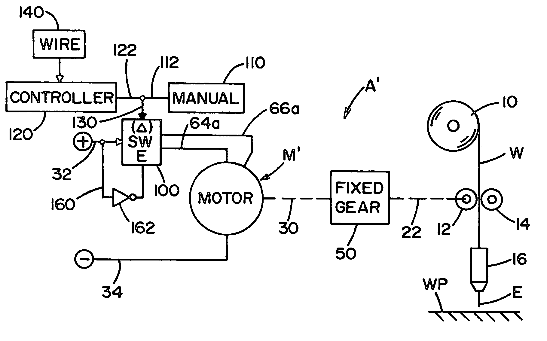
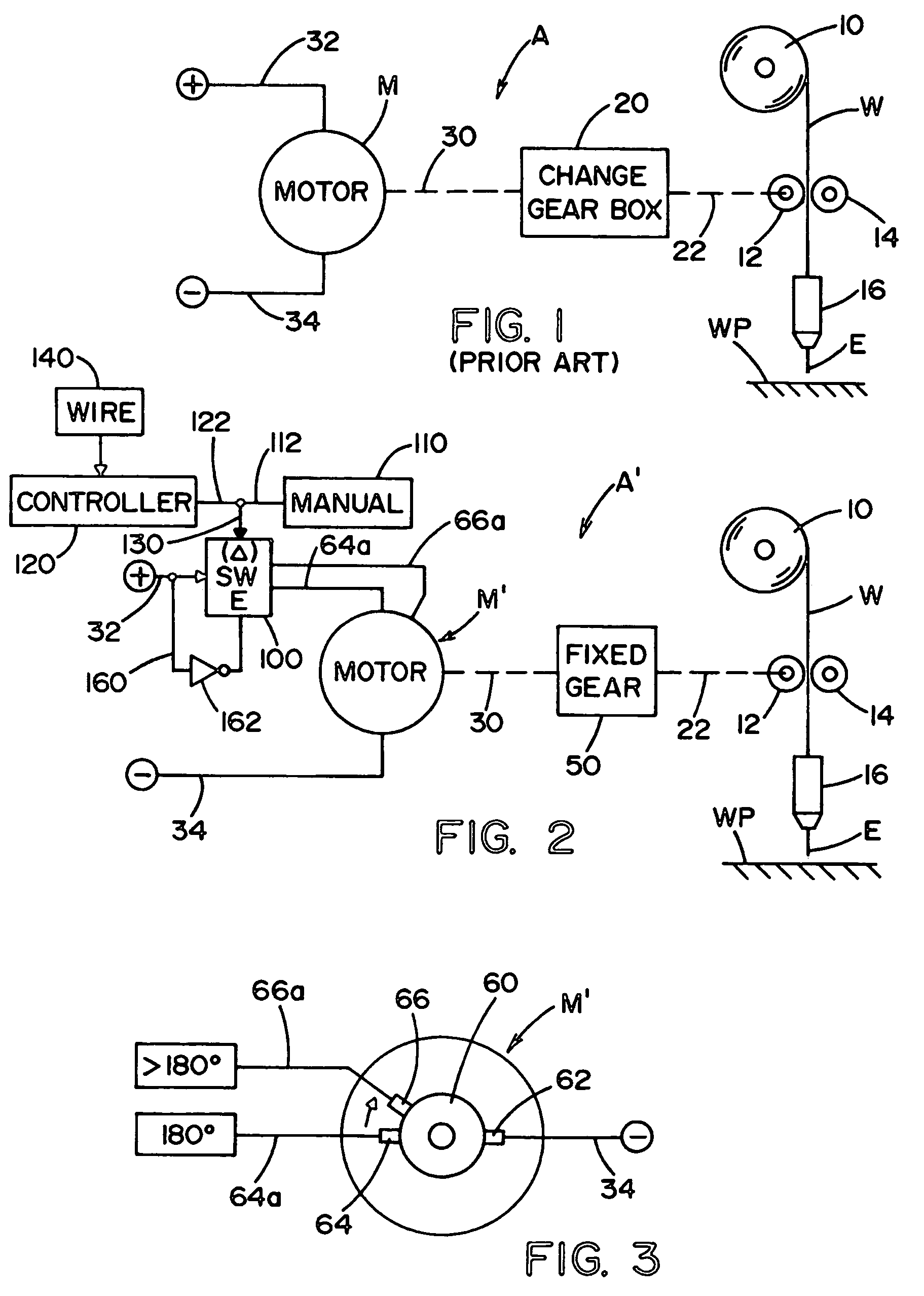
[0016]Referring now to the drawings wherein the showings are for the purpose of illustrating the preferred embodiment of the invention only, and not for the purpose of limiting same, FIG. 1 shows a prior art wire feeder A for an electric arc welder, where welding wire W is provided by spool 10 through drive rolls 12, 14 to a welding gun or torch 16 for creating a welding operation between electrode E and workpiece WP. Box 20 is a gear reducer and has an output shaft 22 for driving rolls 12, 14 in accordance with standard technology. Input shaft 30 for gear box 20 is the output shaft of motor M receiving power from opposite polarity leads 32, 34. Of course, the voltage on these leads is adjusted by a microprocessor or other controller to determine the actual wire feed speed (WFS) utilizing the relationship of the motor and drive rolls controlled by a gear box 20. During the welding operation, motor M operates in accordance with the voltage on leads 32, 34 to drive the rolls in accord...


PUM

PropertyMeasurementUnit
angleaaaaaaaaaa
speedaaaaaaaaaa
sizeaaaaaaaaaa

Abstract

A wire feeder for an electric arc welder comprising a set of feed rolls driven by a DC motor with a commutator, first and second opposite polarity leads receiving power to drive the motor, and having a first brush at a given position on the commutator and connected to the first lead, a second brush circumferentially spaced from the first brush a first annular distance around the commutator and connectable to the second lead to cause the motor to rotate at a first speed to drive the rolls at a first speed, a third brush circumferentially spaced from the first brush a second annular distance around the commutator and connectable to the second lead to cause the motor to rotate at a second speed to drive the rolls at a second speed, and a switching circuit with an operative condition to connect the second lead to a selected one of the second and third brushes.

Description

[0001]The present invention relates to the art of electric arc welding and more particularly to a novel welding wire feeder and a motor for driving the feed rolls of the wire feeder.INCORPORATION BY REFERENCE[0002]The present invention relates to the concept of changing the nominal speed of the feed rolls in a wire feeder for an electric arc welder. The general speed and torque are controlled by a motor that drives a gear box as shown in Rigdon U.S. Pat. No. 6,066,833 (FIG. 9) and Blank U.S. Pat. No. 6,427,894 (FIG. 4) The actual wire feed speed is changed by a controller, but the invention relates to the nominal speed determined by the motor and gear box of these prior art patents. They are incorporated by reference as background information.BACKGROUND OF INVENTION[0003]Electric arc welders include a wire feeder for feeding welding wire from a spool through a welding torch or gun to a welding operation. Such feeders normally include a DC motor for rotating the drive rolls by which ...

Claims


Application Information

Patent Timeline
Patent Type & Authority Patents(United States)
IPC IPC(8): H01R39/38B23K9/12B23K9/133H02P7/00
CPCB23K9/1336B23K9/125
Inventor ENYEDY, EDWARD A.CLARK, KEITH L.
Owner LINCOLN GLOBAL INC
Why Eureka
Try Eureka