Focusing systems for perspective dimensional measurements and optical metrology

a technology of focusing system and perspective dimensional measurement, applied in the field of optical metrology, can solve the problems of loss of calibration, no inherent ability of the user to make a quantitative measurement of the size of the object he or she is viewing, and new optical calibration may have to be performed, so as to achieve more accurate measurements

Inactive Publication Date: 2007-01-09
SCHAACK DAVID F
View PDF11 Cites 24 Cited by
  • Summary
  • Abstract
  • Description
  • Claims
  • Application Information

AI Technical Summary

Benefits of technology

[0036]Accordingly, the present invention has two overarching goals, which are:1. Provide apparatus and methods that enable a user to adjust the focus of an optical metrology system while maintaining measurement accuracy, without requiring recalibration.2. Make the apparatus as simple and inexpensive as possible.
[0037]In order to logically and systematically gain control of the independent variables in an optical system so that these goals can be met, I have developed several new concepts related to an optical system. Using these concepts, I have been able to reduce the number of separately instrumented moving components that are necessary in a variable focus metrological optical system. I have also been able to reduce the requirements on the precision to which the focus motion must be instrumented.

Problems solved by technology

While endoscopes (both flexible and rigid) can give the user a relatively clear view of an inaccessible region, there is no inherent ability for the user to make a quantitative measurement of the size of the objects he or she is viewing.
Making a truly accurate measurement under these circumstances is a long-standing problem that has not been adequately solved until recently.
The problem is that a new optical calibration may have to be performed each time the focus of the instrument is adjusted.
When a standard borescope is used with my previous invention, there is the further difficulty that when an image sensor is mounted to the borescope to perform perspective measurements and the assembly is then calibrated, this calibration is lost if the image sensor is subsequently removed from the borescope.
The fundamental problem with this approach to making accurate dimensional measurements is that the position at which the image is in focus is difficult to determine, thus the range measurement, and hence the magnification, is subject to relatively large random errors (that is, a lack of repeatability).
As a result, these instruments, as disclosed and in practice, are restricted to making two dimensional measurements, i.e., measurements of distances that are oriented perpendicular to the optical axis.
This assumption cannot apply to any three-dimensional measurement technique because the measurement determines the depth of an object, while only a single plane of the object can truly be in focus at a time.
These techniques have the same problem as does the measurement by focus technique when it comes to accurate metrology.
While the system taught by Watanabe and Nayar meets the goals they set for it, their teachings are far from complete.
In addition, their teachings are in error in an important point, in that they state that their system will also work if the lens is moved with respect to the image viewing plane.
The problem addressed by Quinn was that objects near the edge of the field of view of a video or movie camera would be seen to move into or out of the field of view as the focus of the camera was changed.
For the purposes of endoscopic dimensional measurements, the fixed focal length constant absolute magnification systems are not applicable, since the distance between the object and the optical system cannot, in general, be controlled to adjust the magnification.
The variable focal length systems could be applied to these measurements as well as to general optical metrology, but systems using two instrumented moving components are complex and expensive.
In addition, because the disclosed systems have been designed for photography and not metrology, they do not produce the information necessary for accurate metrology.
It has not been well understood that accurate measurements can be made with out of focus images.
This problem has heretofore not been addressed in a comprehensive or coherent manner.
None of the prior art systems is capable of providing the required information about how the magnification, the position of the optical axis, and the distortion depend on the independent variables, nor can they incorporate any such information into the measurement.
Thus, the teachings of the prior art are not sufficient to enable one to perform accurate three-dimensional metrology while also allowing an adjustment of focus to best view an object of interest, without also requiring a recalibration when the focus is adjusted.

Method used


Image

  • Focusing systems for perspective dimensional measurements and optical metrology
  • Focusing systems for perspective dimensional measurements and optical metrology
  • Focusing systems for perspective dimensional measurements and optical metrology

Examples


first embodiment

2. Description of a First Embodiment

[0139]In FIG. 6 is shown an overall perspective view of a video borescope system that provides the ability to focus on objects of interest at various distances, while not requiring an optical calibration when the focus is changed. In the Figure, a rigid borescope 2 has attached at its proximal end a measurement mechanical interface 730 that in turn has attached at its proximal end a measurement video camera 760. Measurement video camera 760 includes on its outer surface a measurement focusing ring 762 and also a video connector 764. This improved video borescope system is meant to be used instead of the standard video borescope system in the perspective measurement system that was fully disclosed in the referenced co-pending applications.

[0140]While the ensuing discussion will be specific to the use of the invention with a rigid borescope, there is nothing that prevents my system from being used with a flexible endoscope as well, and such use is i...

third embodiment

9. Description of a Third Embodiment

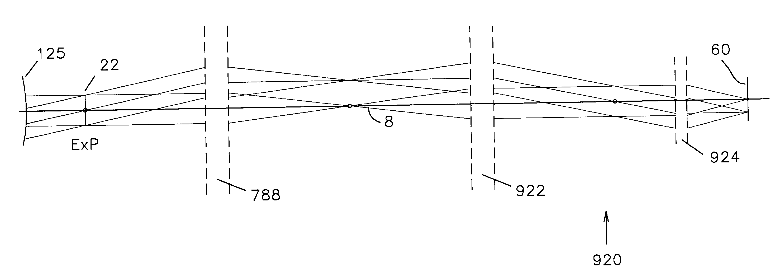
[0409]The optical system of a third embodiment of a measurement camera for use with a borescope is depicted in FIG. 31. The left hand side of this Figure is the same as FIG. 11, because the optical system is a modification of that of the first embodiment. As in the first embodiment, a most proximal lens vertex 125 of a borescope is shown, as is also a borescope exit pupil 22. A projection lens 788 is located centered on optical axis 8 at a distance of one focal length away from exit pupil 22, just as in the first embodiment.

[0410]At the right hand side of FIG. 31 is a generic image sensing plane 60. The sensing plane is denoted by a different number than it was in either of the first two embodiments to indicate the fact that with this third system, no particular sort of image sensing plane is preferred.

[0411]Located between projection lens 788 and image sensing plane 60 is an afocal focusing lens group 920 that consists of a first focusing lens 92...


PUM


Abstract

Focusing systems for which variation of magnification with focus is either inherently compensated, or is calibrated and corrected. The required conditions for inherent compensation are determined, and the desired state is called constant relative magnification. It is shown that telecentricity does not guarantee constant relative magnification. Both telecentric and non-telecentric accessory cameras for endoscopes are disclosed that have constant relative magnification, as are additional optical systems for general metrological purposes. Methods for calibrating change in relative magnification and deviation of the optical axis with focal shift are disclosed, as are methods for incorporating these changes into perspective dimensional measurements. Embodiments are disclosed in which only a single quantity need be measured to perform the correction, and these embodiments require only a low-resolution position transducer to provide accurate measurements. Apparatus is disclosed that enables an accessory camera to be aligned to an endoscope using only externally accessible adjustments. This apparatus also makes it possible to de-mount the camera from one endoscope and re-mount it to another without requiring any recalibration.

Description

CROSS REFERENCE TO RELATED APPLICATIONS[0001]This is a division of Ser. No. 09 / 354,817, filed Jul. 17, 1999 now U.S. Pat. No. 6,476,979.STATEMENT REGARDING FEDERALLY SPONSORED RESEARCH AND DEVELOPMENT[0002](Not Applicable)BACKGROUND OF THE INVENTION[0003]1. Field of the Invention[0004]This invention relates to optical metrology, and particularly to the problem of making accurate non-contact dimensional measurements of objects that are viewed through an endoscope.[0005]2. Description of Related Art[0006]2a. Perspective Dimensional Measurements with Endoscopes[0007]In the past several decades, the use of optical endoscopes has become common for the visual inspection of inaccessible objects, such as the internal organs of the human body or the internal parts of machinery. These visual inspections are performed in order to assess the need for surgery or equipment tear down and repair; thus the results of the inspections are accorded a great deal of importance. Accordingly, there has bee...

Claims


Application Information

Patent Timeline
Patent Type & Authority Patents(United States)
IPC IPC(8): G02B15/14G02B7/04G02B23/24
CPCG02B23/2407G02B7/04
Inventor SCHAACK, DAVID F.
Owner SCHAACK DAVID F
Why Eureka
Try Eureka