Motor Vehicle Navigation System

a technology for motor vehicles and navigation systems, applied in traffic control systems, beacon systems, instruments, etc., can solve the problems of large data bus bandwidth, inability to ensure continuous and thus flowing display of geographical contents, and inability to transfer other information or data, etc., to facilitate expansion or replacement of individual components, reduce bandwidth, and save time

Inactive Publication Date: 2007-01-09
AG BECKER & CO
View PDF21 Cites 10 Cited by
  • Summary
  • Abstract
  • Description
  • Claims
  • Application Information

AI Technical Summary

Benefits of technology

[0014]In general, modularization facilitates expansion or replacement of individual components. The maximum measure of flexibility in this regard is achieved by the invention in that the navigation computer and the monitor are designed as modules, each of which separately has a microprocessor / computer.
[0015]Since a vehicle normally moves continuously, suitable data management in the monitor unit may detect at an early stage what road map information will subsequently be needed due to the vehicle motion. This can be requested from the navigation computer prospectively (look-ahead principle), so that more time is available for its transmission. This also helps to reduce the need for bandwidth on the data bus, and thus correspondingly relieves the network.
[0016]The data bus is preferably configured and arranged as a “Media Oriented Synchronous Transfer” (MOST) bus or as a “Multi Media Link” (MML) bus. In combination with the modular structure of the present invention, standardized buses such as these ensure that the inventive navigation system can easily be integrated into nearly all current vehicle brands.

Problems solved by technology

For a screen display with sufficient picture refresh cycles, the data bus must have a large bandwidth, which generally often not available.
An additional problem is that the data bus is needed almost exclusively for transferring picture information, and therefore other information or data cannot be transferred, or can be transferred only serially during the remaining interim times.
Furthermore, a continuous and thus flowing display of geographical contents is not assured, because the screen shows only the data transferred over the data bus, and the data capacity that can be transferred on the bus is limited.
Because the capacity of the bus is limited and because of the bus latency times, scroll or zoom operations, for instance, often cause dramatic picture changes that are perceived as troublesome by the viewer.
A problem with these prior art systems is that the geographical map for the display is calculated by the navigation computer.
That is, there is no “intelligent” processing of the received data.

Method used


Image

  • Motor Vehicle Navigation System
  • Motor Vehicle Navigation System
  • Motor Vehicle Navigation System

Examples


Embodiment Construction

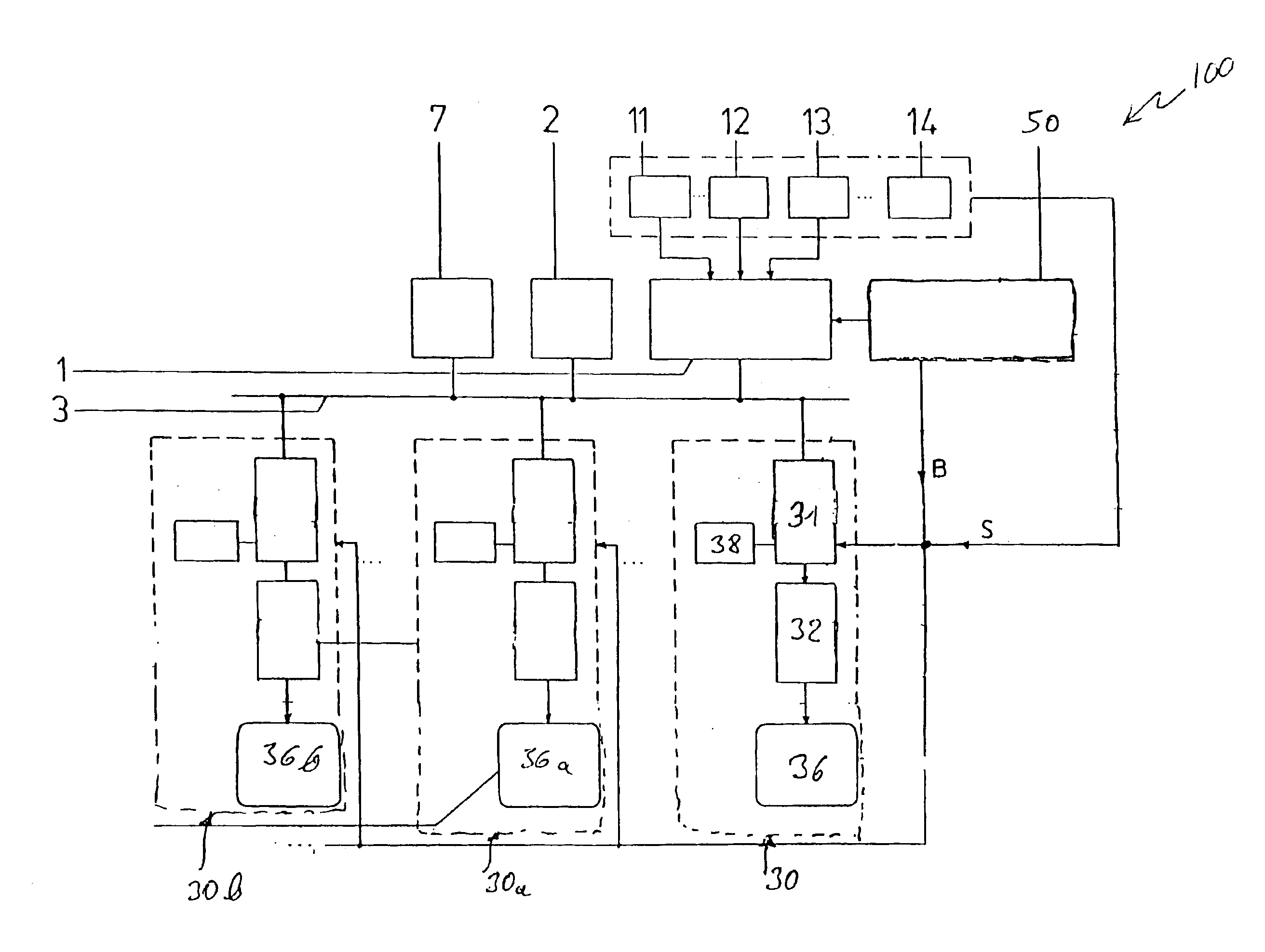
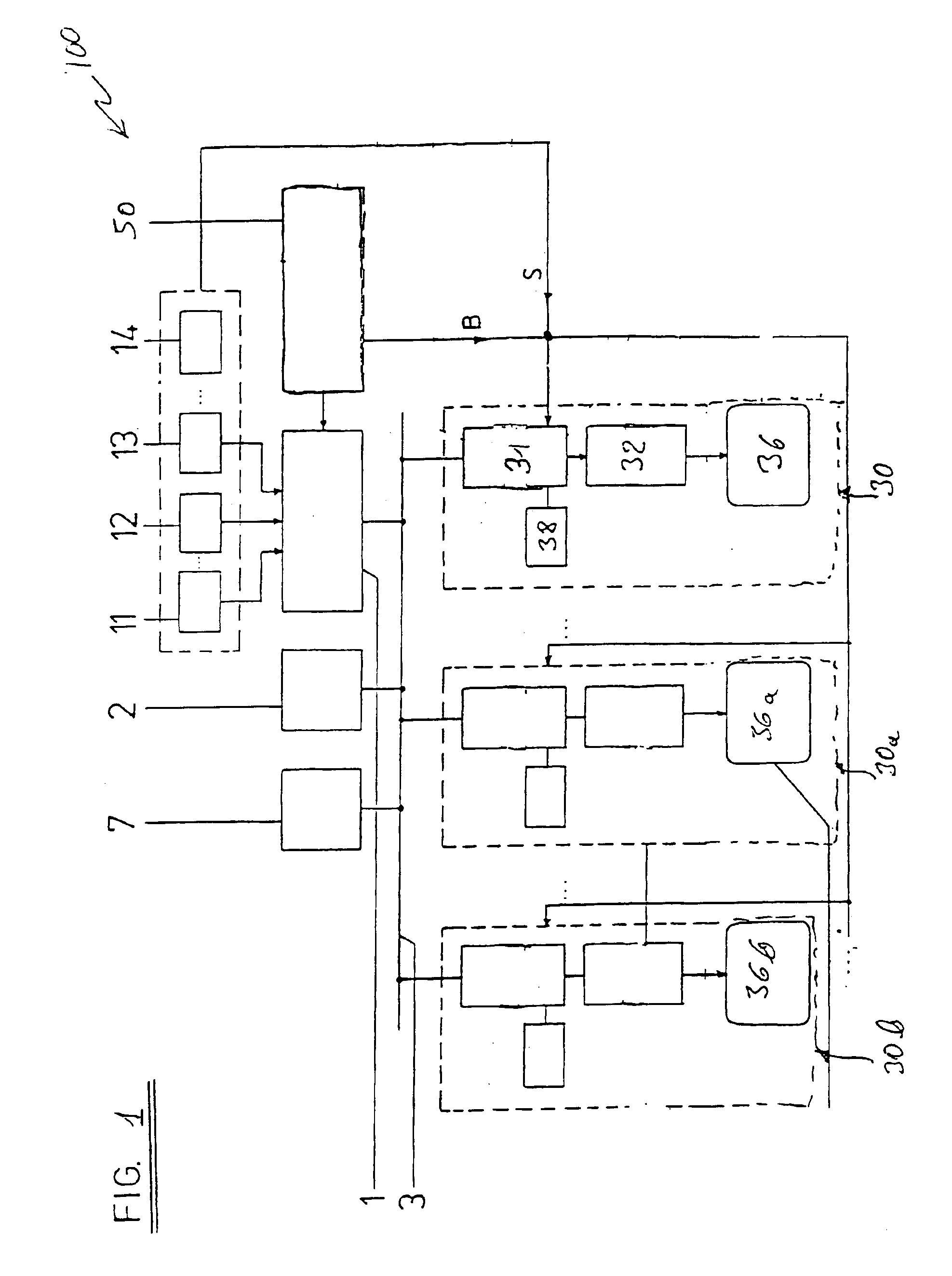
[0022]FIG. 1 is a block diagram illustration of a motor vehicle navigation system 100. The navigation system 100 includes a navigation computing unit 1, a data memory 2, a monitor unit 30, and various other components 7, each connected to a data bus 3 (e.g., an optical bus such as a MOST or MML bus). The navigation computer 1 is connected to a mass storage medium 50 (e.g., a CD drive) in order to retrieve road map information stored thereon. The navigation system 100 receives data signals from a speedometer 11, a direction sensor 12, a position sensor 13, and a tachometer 14. The monitor unit 30 includes an internal computer 31, a memory device 32, a display 36, and control elements 38.

[0023]The road map information in the navigation computer 1 is present as a geographical coordinate system (e.g., the WGS 84 coordinate system). The navigation computer 1 accesses such a geographical coordinate system for example through the above-mentioned mass storage unit 50. To generate a map to b...


PUM


Abstract

A motor vehicle navigation system comprises a position sensor that senses the geographical position of the navigation system and provides a first navigation system position signal indicative thereof. The navigation system system also includes a navigation computing unit that recieves the first navigation system position signal and transmits onto a data bus (i) a first position signal indicative of the position of a trip starting location, (ii) a second position signal indicative of a trip destination location and (iii) the first navigation system position signal. A road map memory device includes map data. A second computing unit recieves (i) the first position signal, (ii) the second position signal and (iii) the first navigaion system position signal and the map data, and generates initial image data including map data indicative of the trip starting location, the trip destination location and the current position of the navigation system, and a display displays an initial image indicative of the initial image data.

Description

BACKGROUND OF THE INVENTION[0001]The present invention relates to the field of motor vehicle navigation systems, and in particular to a motor vehicle navigation system that includes a modular display computing system for presenting navigational data to a motor vehicle user.[0002]Navigation systems are increasingly being used in motor vehicles. These systems generally include: (i) a control unit for entering the starting location, any intermediate destinations, and the final destination; (ii) a data medium for storing navigational data (e.g., information to display road maps); (iii) a navigation computer to plan / compute the route and provide guidance to the destination; (iv) a data processing unit to process the route data into picture information; and (v) a display to display road maps, position information, destination information, etc. The navigation system also includes a plurality of sensors to determine the vehicle's position, speed, orientation, etcetera and provide that infor...

Claims


Application Information

Patent Timeline
Patent Type & Authority Patents(United States)
IPC IPC(8): G01C21/00G01C21/36
CPCG01C21/3667
Inventor BAHREN, FRANKBECKER, MICHAELSCHOPP, HARALD
Owner AG BECKER & CO
Why Eureka
Try Eureka