
Control system simulation, testing, and operator training

a control system and operator training technology, applied in the field of control system simulation, test, and training systems, can solve the problems of time-consuming, prone to errors, and inability to properly verify the satisfaction of requirements, so as to facilitate the training of operators

Inactive Publication Date: 2007-01-09
FLUOR TECH CORP
View PDF3 Cites 5 Cited by
  • Summary
  • Abstract
  • Description
  • Claims
  • Application Information

AI Technical Summary

Benefits of technology

Enables effective testing and training of control systems, ensuring requirement satisfaction, reducing costs by eliminating the need for large-scale mock-ups and allowing operators to be trained onsite, thereby improving the efficiency and safety of the testing and training processes.

Problems solved by technology

Generating test plans, implementing those plans, and correlating test results with requirements to verify requirement satisfaction can be tedious, time consuming, and prone to errors.
Although methods and devices for testing control systems are known, they generally have individual strengths and weaknesses which make them more appropriate in some situations and less appropriate in others.
A primary weakness of most methods and devices for testing control systems is the inability to properly verify requirement satisfaction.
This inability may be at least partially due to the fact that, once installed in a plant, the controller cannot be subjected to as complete or rigorous testing as it can in a lab environment.
Another possible factor is the difficulty in correlating large amounts of test results to requirements.
In addition to the difficulties associated with testing and verification, training operators to use the HMI portion 910 of a control system can sometimes be difficult to achieve in a cost effective manner.
Training operators on a “live” system (i.e. one already installed in an operating plant) is not a preferred method as it risks damage to the plant, wastage of material and generally requires that the plant be shut down or operated at less than full capacity during training.
It is also often difficult and expensive to keep the mock-up in sync with plant changes.
Moreover, training costs tend to increase substantially if operators must travel to an offsite location to be trained.

Method used


Image

  • Control system simulation, testing, and operator training
  • Control system simulation, testing, and operator training

Examples


example application

[0048

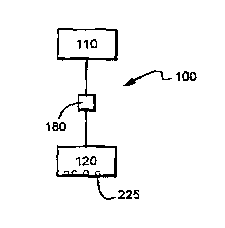
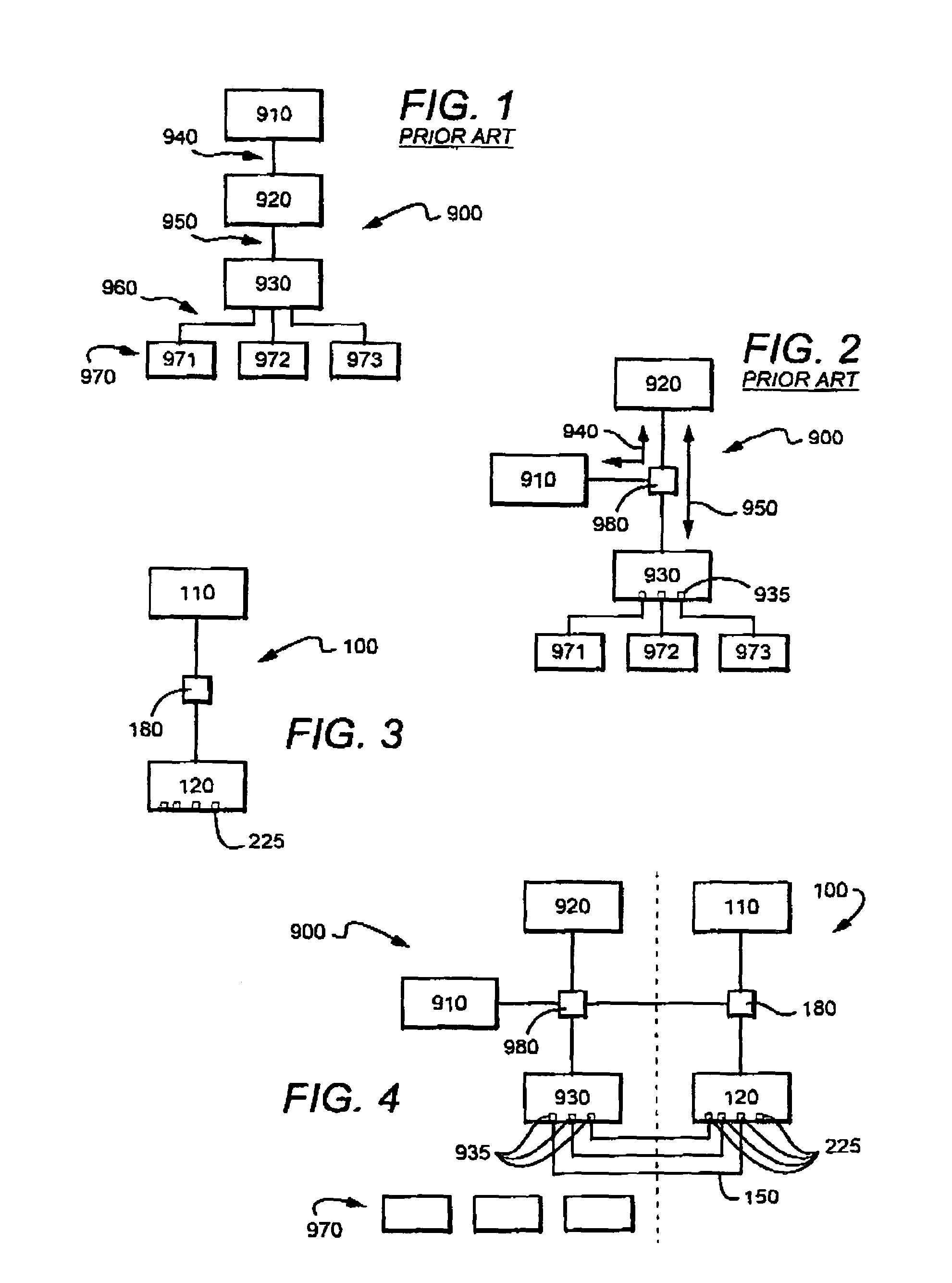
[0049]Test system 100 is contemplated as being particularly well suited for a number of uses when taken to an operational facility and connected in place of all or part of the field wiring including but not necessarily limited to: (1) testing existing logic for reaction to new scenarios; (2) testing new logic for operations; (3) training process operators prior to an operational campaign to a) score and validate operator readiness, b) identify deficient training areas, and c) ensure operational readiness as an overall team; (4) training process operators at the operational facility using by plugging test system 100 in place of the plant's actual sensors and actuators; (4) field trouble shooting of wiring and other field related problems.

[0050]Example—Offsite Testing

[0051]An example application of test system 100 is its in revalidating a PLC program used to manufacture a drug wherein the PLC does so by controlling ingredient weighing, heating, cooling, tank level control, pump c...


PUM


Abstract

A requirements database and test generator generates tests for functional and field testing and generates requirements documentation, user manuals, operational procedures, instrument data sheets, instrument indices, instrument loop diagrams, validation reports, and test reports, including exception and passing reports. A portable process control simulator system which provides control system users with scenarios that mirror field operation as defined.

Description

[0001]This application is a divisional of previously allowed U.S. application with the Ser. No. 10 / 129,464, which was filed Mar. 4, 2003 now U.S. Pat. No. 6,823,280, which is a 371 of International patent application with the serial number PCT / US00 / 07962, which was filed Mar. 23, 2000, and U.S. provisional patent applications with the Ser. Nos. 60 / 177,899 and 60 / 177,991, which were filed Jan. 24, 2000.FIELD OF THE INVENTION[0002]The field of the invention is control system simulation, test, and training systems.BACKGROUND OF THE INVENTION[0003]Control systems incorporating PLCs (Programmable Logic Controlers) and DCSs (Distributed Control Systems) are frequently used to control real world processes by accepting inputs which typically originate from sensors such as, among others, those used to sense temperature, flow, level, radiation, light, movement, and pressure, and those used in generating outputs which are used to drive actuators such as hydraulic devices, valves, lights, and m...

Claims


Application Information

Patent Timeline
Patent Type & Authority Patents(United States)
IPC IPC(8): G06F19/00G01R27/28G05B17/02G01R31/00G01R31/14G05B19/05G05B23/02G06F3/00G06F11/26G09B9/00G09B25/02
CPCG05B19/05G09B25/02G06F11/261G05B2219/13174G05B2219/24061G05B2219/24058
Inventor SCHAROLD, PAUL G.BRAYTON, D. DWIGHTGHORMLEY, CHRISTOPHER S.ADDLEMAN, SHANE R.
Owner FLUOR TECH CORP
Learn More