Parallel flow evaporator with non-uniform characteristics

a technology of parallel flow and evaporator, which is applied in the direction of indirect heat exchangers, lighting and heating apparatus, refrigeration components, etc., can solve the problems of significant evaporator and overall system performance degradation, improper heat exchanger orientation, and possible misdistribution of refrigerant, so as to minimize the effect of heat exchanger performan

Inactive Publication Date: 2007-01-16
CARRIER CORP
View PDF7 Cites 30 Cited by
  • Summary
  • Abstract
  • Description
  • Claims
  • Application Information

AI Technical Summary

Benefits of technology

[0009]Briefly, in accordance with one aspect of the invention, the uneven distribution of refrigerant to the individual channels from the inlet manifold is overcome and compensated by providing non-uniform external heat transfer characteristics associated with the individual channels, such that the detrimental effects of refrigerant maldistribution are counter-balanced, their effect on the heat exchanger performance is minimized and potential flooding conditions at the evaporator exit are avoided.

Problems solved by technology

It causes significant evaporator and overall system performance degradation over a wide range of operating conditions.
Maldistribution of refrigerant may occur due to differences in flow impedances within evaporator channels, non-uniform airflow distribution over external heat transfer surfaces, improper heat exchanger orientation or poor manifold and distribution system design.
Attempts to eliminate or reduce the effects of this phenomenon on the performance of parallel flow evaporators have been made with little or no success.
The primary reasons for such failures have generally been related to complexity and inefficiency of the proposed technique or prohibitively high cost of the solution.
The evaporator applications, although promising greater benefits and rewards, are more challenging and problematic.
Refrigerant maldistribution is one of the primary concerns and obstacles for the implementation of this technology in the evaporator applications.
As known, refrigerant maldistribution in parallel flow heat exchangers occurs because of unequal pressure drop inside the channels and in the inlet and outlet manifolds, as well as poor manifold and distribution system design.
Furthermore, the recent trend of the heat exchanger performance enhancement promoted miniaturization of its channels (so-called minichannels and microchannels), which in turn negatively impacted refrigerant distribution.
Since it is extremely difficult to control all these factors, many of the previous attempts to manage refrigerant distribution, especially in parallel flow evaporators, have failed.
If, on the other hand, the velocity of the two-phase flow entering the manifold is low, there is not enough momentum to carry the liquid phase along the header.
Also, the liquid and vapor phases in the inlet manifold can be separated by the gravity forces, causing similar maldistribution consequences.
In either case, maldistribution phenomenon quickly surfaces and manifests itself in evaporator and overall system performance degradation.
Moreover, maldistribution phenomenon may cause the two-phase (zero superheat) conditions at the exit of some channels, promoting potential flooding at the compressor suction that may quickly translate into the compressor damage.

Method used


Image

  • Parallel flow evaporator with non-uniform characteristics
  • Parallel flow evaporator with non-uniform characteristics
  • Parallel flow evaporator with non-uniform characteristics

Examples


Embodiment Construction

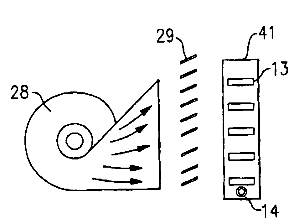
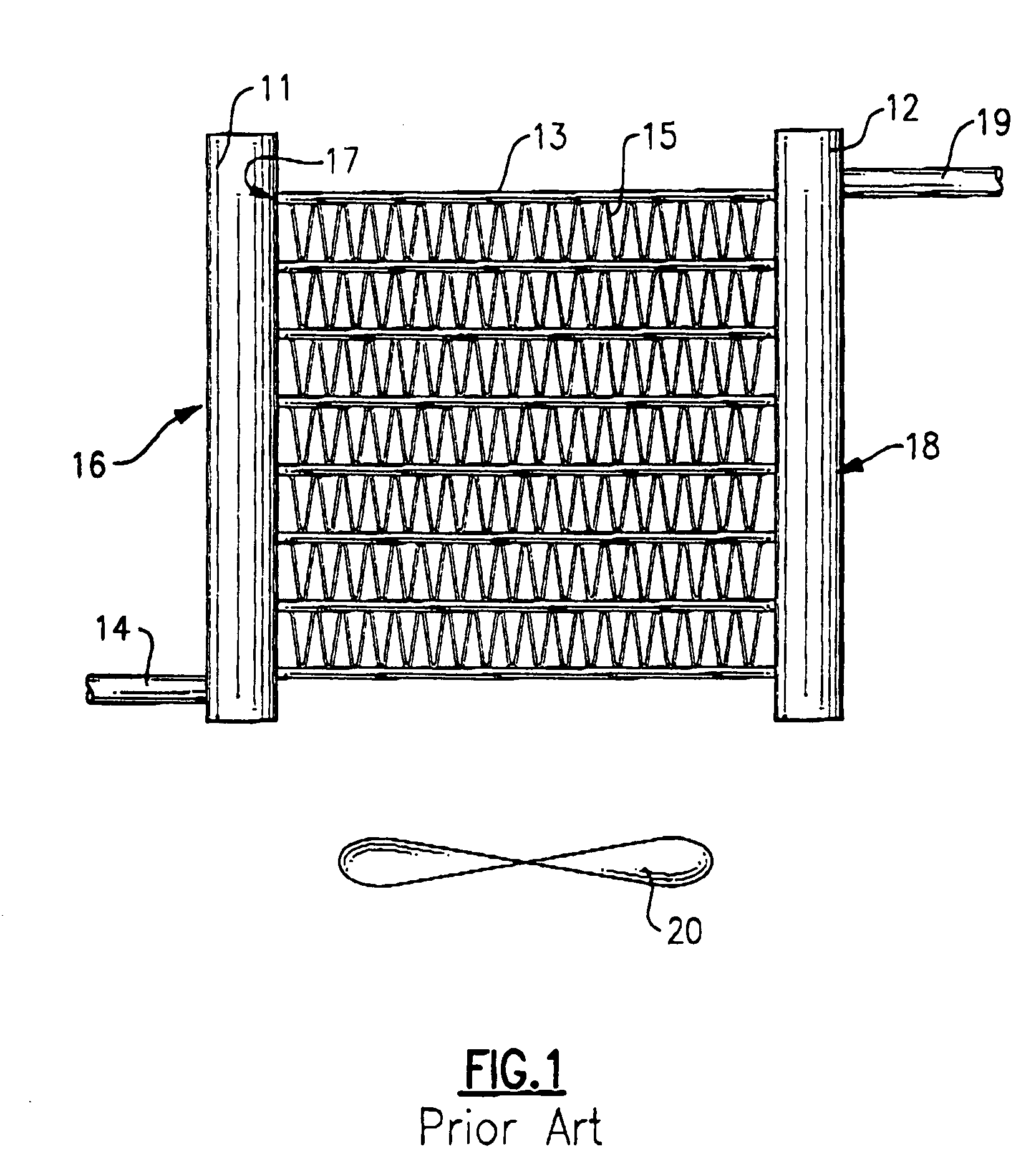
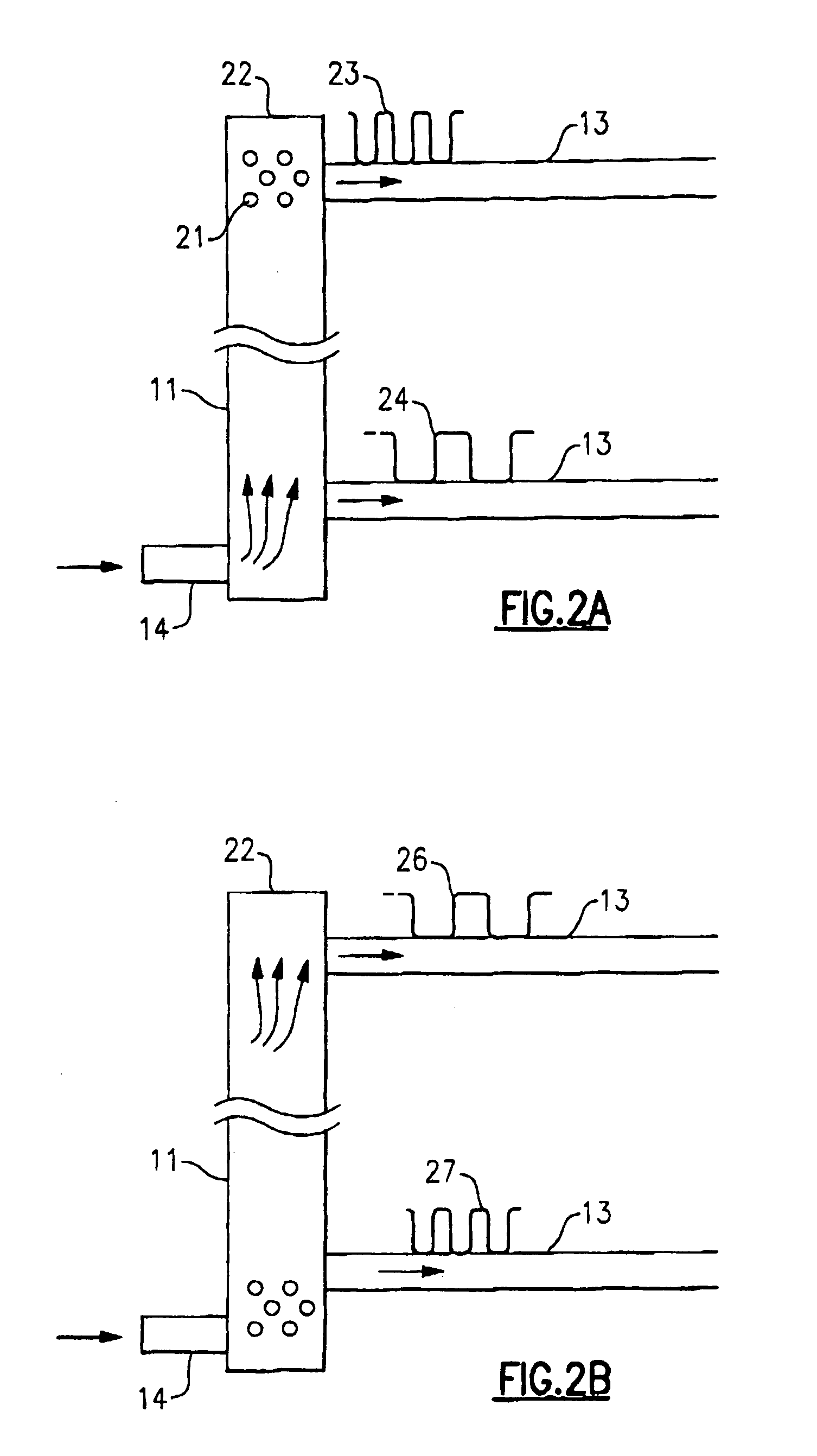
[0018]Referring now to FIG. 1, a parallel flow heat exchanger is shown to include an inlet header or manifold 11, an outlet header or manifold 12 and a plurality of parallel disposed channels 13 fluidly interconnecting the inlet manifold 11 to the outlet manifold 12. Generally, the inlet and outlet headers 11 and 12 are cylindrical in shape, and the channels 13 are tubes (or extrusions) of flattened or round shape. Channels 13 normally have a plurality of internal and external heat transfer enhancement elements, such as fins. For instance, external fins 15, uniformly disposed therebetween for the enhancement of the heat exchange process and structural rigidity are typically furnace-brazed. Channels 13 may have internal heat transfer enhancements and structural elements as well.

[0019]In operation, two-phase refrigerant flows into the inlet opening 14 and into the internal cavity 16 of the inlet header 11. From the internal cavity 16, the refrigerant, in the form of a liquid, a vapor ...


PUM


Abstract

In a parallel flow heat exchanger, which is susceptible to having a non-uniform distribution of a two-phase refrigerant flow to the individual channels, the resultant differences in the refrigerant flow therethrough are compensated and counter-balanced by a corresponding difference in the external heat transfer rate for the respective channels. In one embodiment, these differences are accomplished by variable characteristics of extended heat transfer surface elements such as fin type, fin density, fin geometry and difference in construction materials, and in another embodiment, by varying the airflow distribution over the cross-section area of the heat exchanger.

Description

BACKGROUND OF THE INVENTION[0001]This invention relates generally to air conditioning and refrigeration systems and, more particularly, to parallel flow evaporators thereof.[0002]A definition of a so-called parallel flow heat exchanger is widely used in the air conditioning and refrigeration industry now and designates a heat exchanger with a plurality of parallel passages, among which refrigerant is distributed and flown in the orientation generally substantially perpendicular to the refrigerant flow direction in the inlet and outlet manifolds. This definition is well adapted within the technical community and will be used throughout the text.[0003]Refrigerant maldistribution in refrigerant system evaporators is a well-known phenomenon. It causes significant evaporator and overall system performance degradation over a wide range of operating conditions. Maldistribution of refrigerant may occur due to differences in flow impedances within evaporator channels, non-uniform airflow dis...

Claims


Application Information

Patent Timeline
Patent Type & Authority Patents(United States)
IPC IPC(8): F28D1/053
CPCF25B39/02F28F13/06F28D1/05366F28F9/0268F28D1/024F25B2500/01
Inventor TARAS, MICHAEL F.KIRKWOOD, ALLEN C.CHOPKO, ROBERT A.
Owner CARRIER CORP
Why Eureka
Try Eureka