
Integrated wireless distribution and mesh backhaul networks

a wireless distribution and mesh technology, applied in the field of wireless communications, can solve the problems of large burden on the backhaul network feeding the cell size of the area serviced by the localized wireless nodes, and the network is backhaul data transmission

Active Publication Date: 2007-01-16
WI FI ONE
View PDF19 Cites 132 Cited by
  • Summary
  • Abstract
  • Description
  • Claims
  • Application Information

AI Technical Summary

Benefits of technology

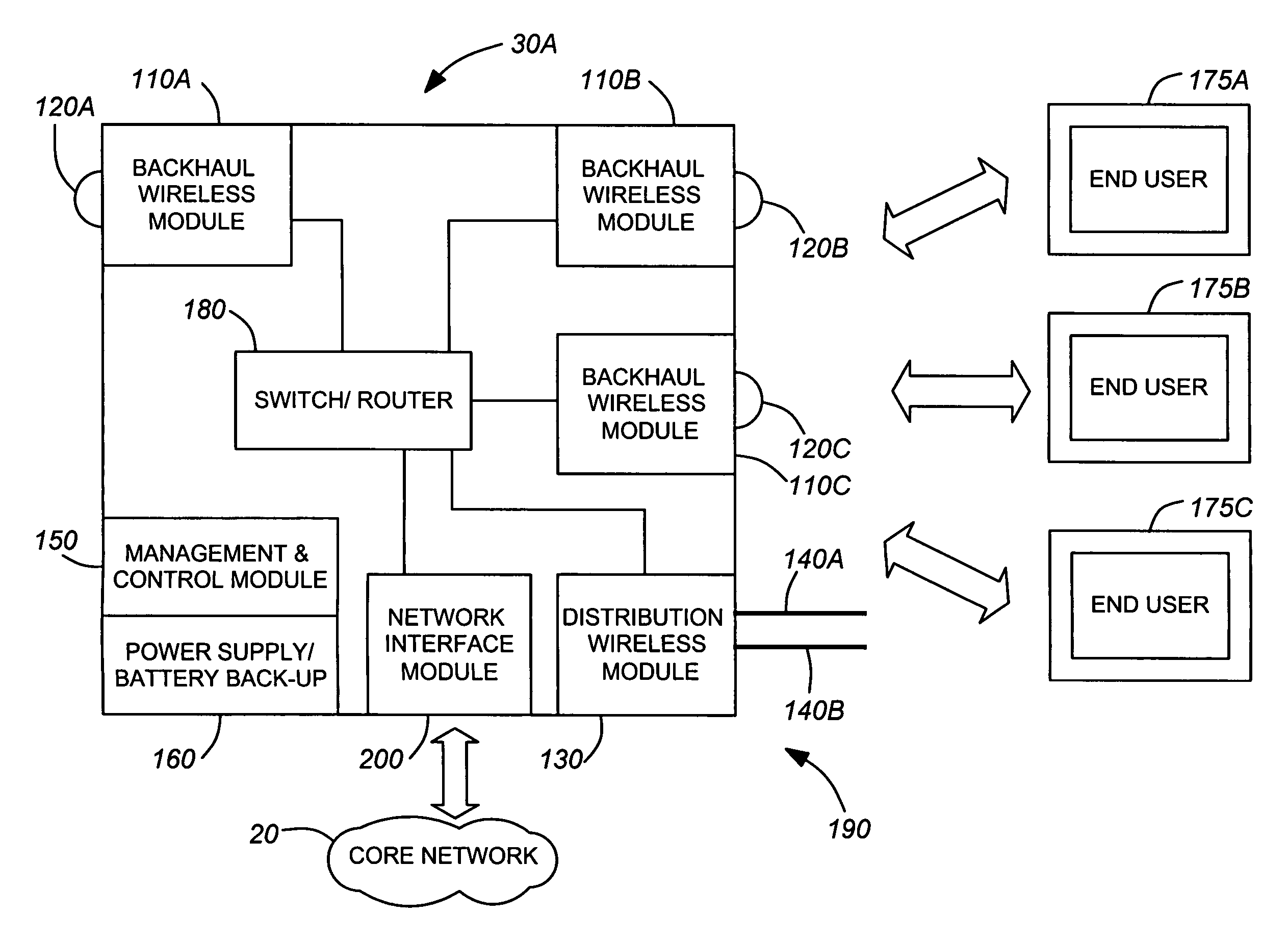
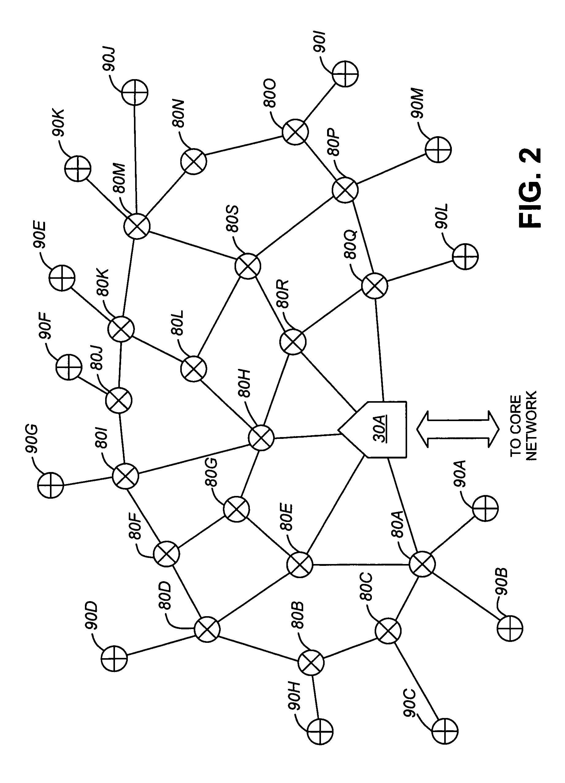
[0010]The present invention provides networks, devices and methods related to wireless networking. A wireless network using nodes that perform both distribution and backhaul functions is provided. These nodes constitute the key elements of a wireless network that would be deployed and controlled by a wireless network operator. Each node contains a distribution wireless module which is wirelessly coupled to the wireless end user device using a point to multipoint scheme. Also integrated into each node is at least one backhaul wireless module with a directional wireless antenna. Each backhaul wireless module communicates by way of a point to point wireless link with the backhaul module of one other node. The nodes in the wireless network are interconnected to form a mesh backhaul network. Because of the nature of a mesh network, data traffic can be routed around obstacles that may prevent line of site links. Furthermore, the mesh network allows dynamic routing of data traffic to avoid congestion points or downed links in the network.
[0044]e) determining routing paths from said specific node to each of said other nodes based on said data calculated in b) and said link data received from other nodes in step c) such that a path cost associated with said routing path is minimized,

Problems solved by technology

One major problem facing wireless networks is backhaul data transmission.
As cellular and PCS voice utilization inside buildings increases and as the data transfer rate provided to the end user increases, the backhaul network feeding the localized wireless nodes gets heavily burdened.
Further, as wireless data speed requirements increase, cell sizes—the area serviced by the localized wireless nodes—must shrink.
Because of the above, high speed, high capacity wireless networks have generally been limited by backhaul bandwidth.
Such bandwidth, previously provided by copper, optical or microwave radio links, comes at a very great cost to the operator and deployer of the wireless network.
However, network designers do face difficulties in using wireless technology to link the wireless nodes (which distribute the signals to a wireless end user) back to the wired network.
However, many deployments, such as in dense urban areas, do not allow for line of sight links from all wireless nodes to the wired network interface.
Even if line of sight is possible, the variable propagation performance of wireless links and the constant changes in the nature and location of traffic demand make dedicated point to point links less than optimal.
In addition, hauling all links back to a central point leads to high signal congestion at that point.
Previous attempts to remedy the above issues have met with limited success.
Unfortunately, the system suffers from the possibility of signal congestion at both the repeater and the relay nodes.
Unfortunately, the performance of this type of network is highly dependent on the presence and location of the subscriber's equipment.
It suffers from limits to scalability—since each subscriber node is potentially a connecting link for all traffic, each subscriber node can potentially become clogged with data traffic.
In addition, there are problems in seeding initial network coverage.
Furthermore, there is a greater potential lack of privacy between subscribers since each node can become an intercept point for network wide data leaks.
Unfortunately, this approach requires large numbers of end user devices in a given area to work properly.
Furthermore, the unpredictable nature of the end users' presence and location, most of whose devices will form part of the routing network, makes for unpredictable and potentially unreliable system availability and performance.

Method used


Image

  • Integrated wireless distribution and mesh backhaul networks
  • Integrated wireless distribution and mesh backhaul networks
  • Integrated wireless distribution and mesh backhaul networks

Examples


Embodiment Construction

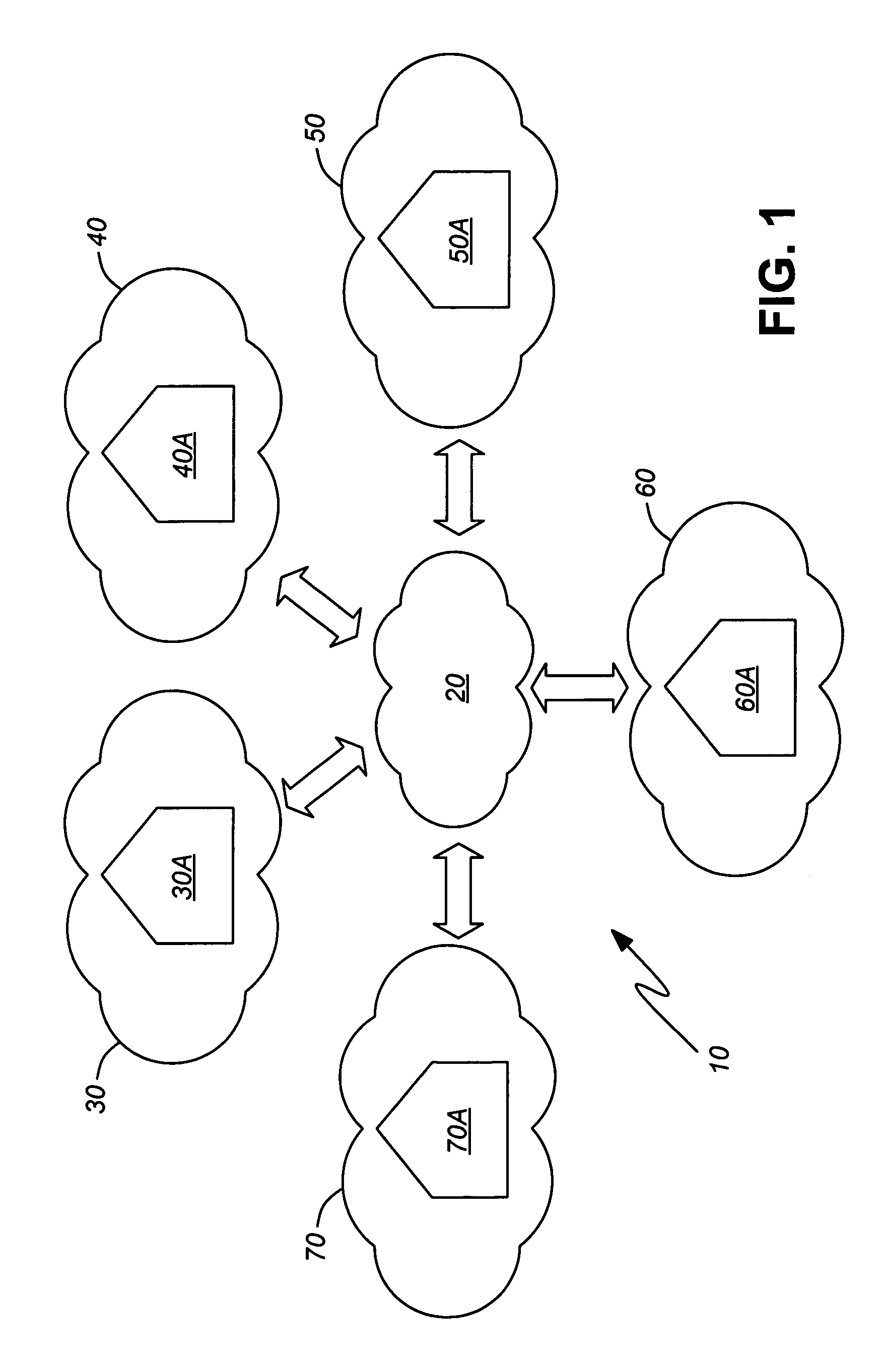
[0052]Referring to FIG. 1, a block diagram of a large network 10 is illustrated. The network 10 consists of a core network 20 and wireless networks 30, 40, 50, 60, 70, each of which has a network aggregation node 30A, 40A, 50A, 60A, 70A. The core network 20 may be a public and / or private, voice and / or data network. Each wireless network covers a specific geographic region. Each network aggregation node 30A–70A directly connects to the core network 20 by conventional means such as copper wire, fiber optic cable or microwave radio transmission. Each network aggregation node 30A–70A then distributes data from the large network to end users within the geographic region of the coverage of its wireless network.

[0053]Referring to FIG. 2, a block diagram of the wireless network 30 in FIG. 1 is illustrated. As can be seen, the network aggregation node 30A is connected to a core network as shown previously in FIG. 1. The wireless network 30 consists of a wireless network aggregation node 30A,...


PUM


Abstract

Networks, devices and methods related to wireless networking. A wireless network using nodes that perform both distribution and backhaul functions is provided. These nodes constitute the key elements of a wireless network that would be deployed and controlled by a wireless network operator. Each node contains a distribution wireless module which is wirelessly coupled to the wireless end user device using a point to multipoint scheme. Also integrated into each node is at least one backhaul wireless module with a directional wireless antenna. Each backhaul wireless module communicates by way of a point to point wireless link with the backhaul module of one other node. The nodes in the wireless network are interconnected to form a mesh backhaul network. Because of the nature of a mesh network, data traffic can be routed around obstacles that may prevent line of site links. Furthermore, the mesh network allows dynamic routing of data traffic to avoid congestion points or downed links in the network.

Description

FIELD OF THE INVENTION[0001]The present invention relates to wireless communications and is particularly applicable but not limited to networks, devices and methods for flexible, high capacity, integrated wireless distribution and mesh point to point backhaul networks.BACKGROUND TO THE INVENTION[0002]The communications revolution of the past few years has seen an explosion in the number of wireless devices. Cellular telephones, personal digital assistants (PDAs), laptops, and other consumer devices are using wireless technology to provide connectivity to their users. Wireless technology is currently being used to provide voice-based services for cellular and PCS (Personal Communication Services) telephones, with increasing need for into building coverage. PDAs and laptops can now access the Internet and local dedicated intranets, giving end users access to not only email but also to World Wide Web based content. The increased demand for access to more services in more locations impo...

Claims


Application Information

Patent Timeline
IPC IPC(8): H04Q7/00H04L12/28H04L12/56H04W28/08H04W40/00H04W40/02H04W40/06H04W40/24H04W84/00
CPCH04L45/02H04L45/124H04W84/00H04W28/08H04W40/02H04W40/06H04W40/246H04W40/00
Inventor RAYMENT, STEPHEN G.HERSCOVICH, BERNARD
Owner WI FI ONE
Learn More