Voice storage device and voice coding device

a voice storage and voice technology, applied in the field of voice storage devices and voice coding devices, can solve the problems of not being able to achieve the requested degree of voice recording time, heavy restriction of the capacity of the semiconductor memory that can be incorporated into the terminal, etc., and achieve the effect of improving the missing voice and the residual capacity of the recording medium

Inactive Publication Date: 2007-01-16
OKI ELECTRIC IND CO LTD
View PDF24 Cites 12 Cited by
  • Summary
  • Abstract
  • Description
  • Claims
  • Application Information

AI Technical Summary

Benefits of technology

[0007]The present invention has been made in view of the technical difficulties of precisely detecting a voice interval, and it is an object of the invention to provide an implement that enables a clear recording of a message voice when the residual capacity of a recording medium is ample, and enables a significant improvement of the missing of a voice, especially the missing at the beginning of a word when the residual capacity becomes marginal.

Problems solved by technology

But, because of the user's demand for the miniaturization of the terminal, there is a heavy restriction to the capacity of the semiconductor memory that can be incorporated into the terminal.
Accordingly, the use of the normal CELP system could not have realized a sufficient voice recording time to a requested degree.

Method used


Image

  • Voice storage device and voice coding device
  • Voice storage device and voice coding device
  • Voice storage device and voice coding device

Examples


first embodiment

(1) First Embodiment

[0022]The first embodiment of a voice storage device and a voice coding device according td the invention will now be discussed with reference to the accompanying drawings.

(1-1) Configuration of the First Embodiment

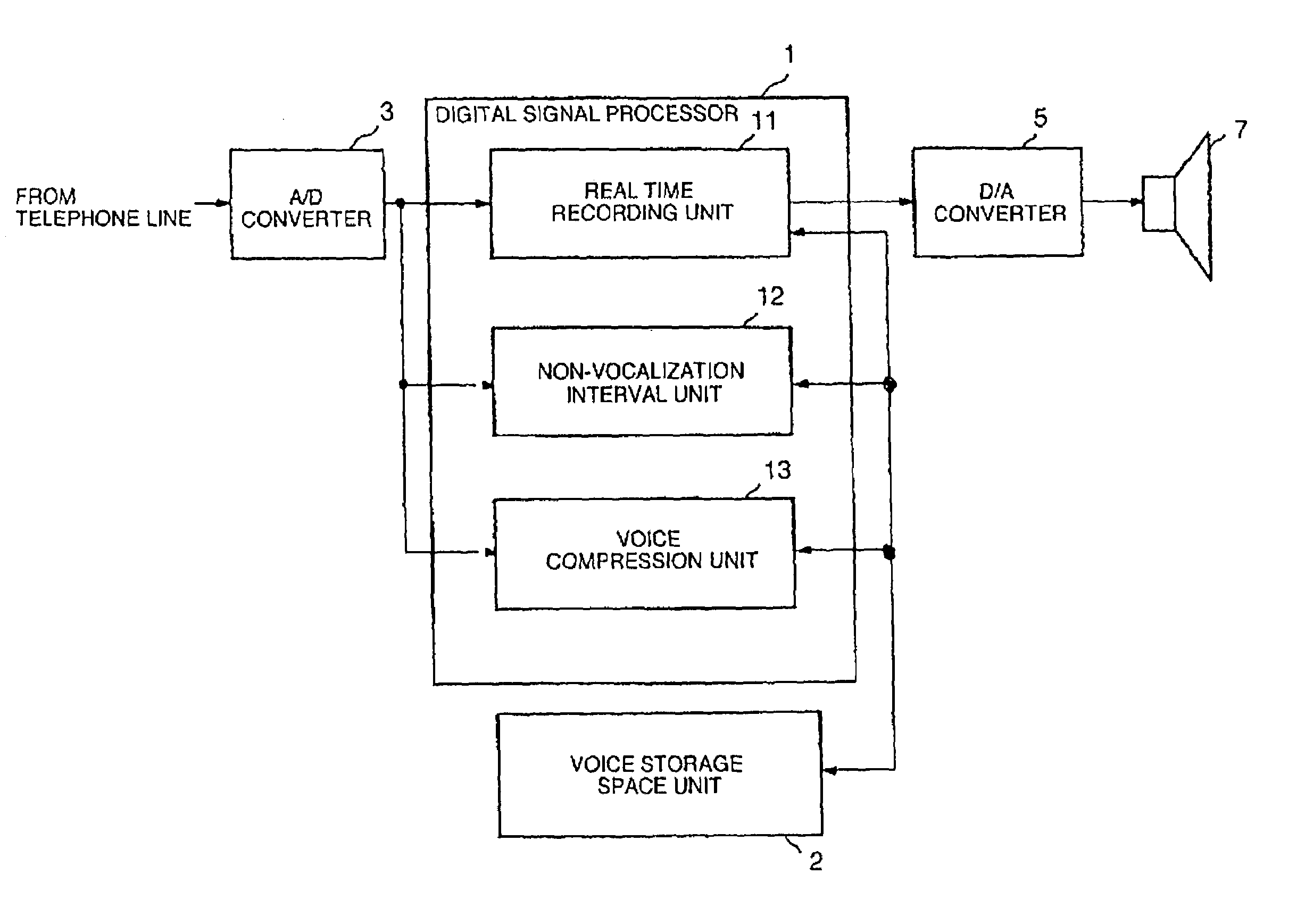
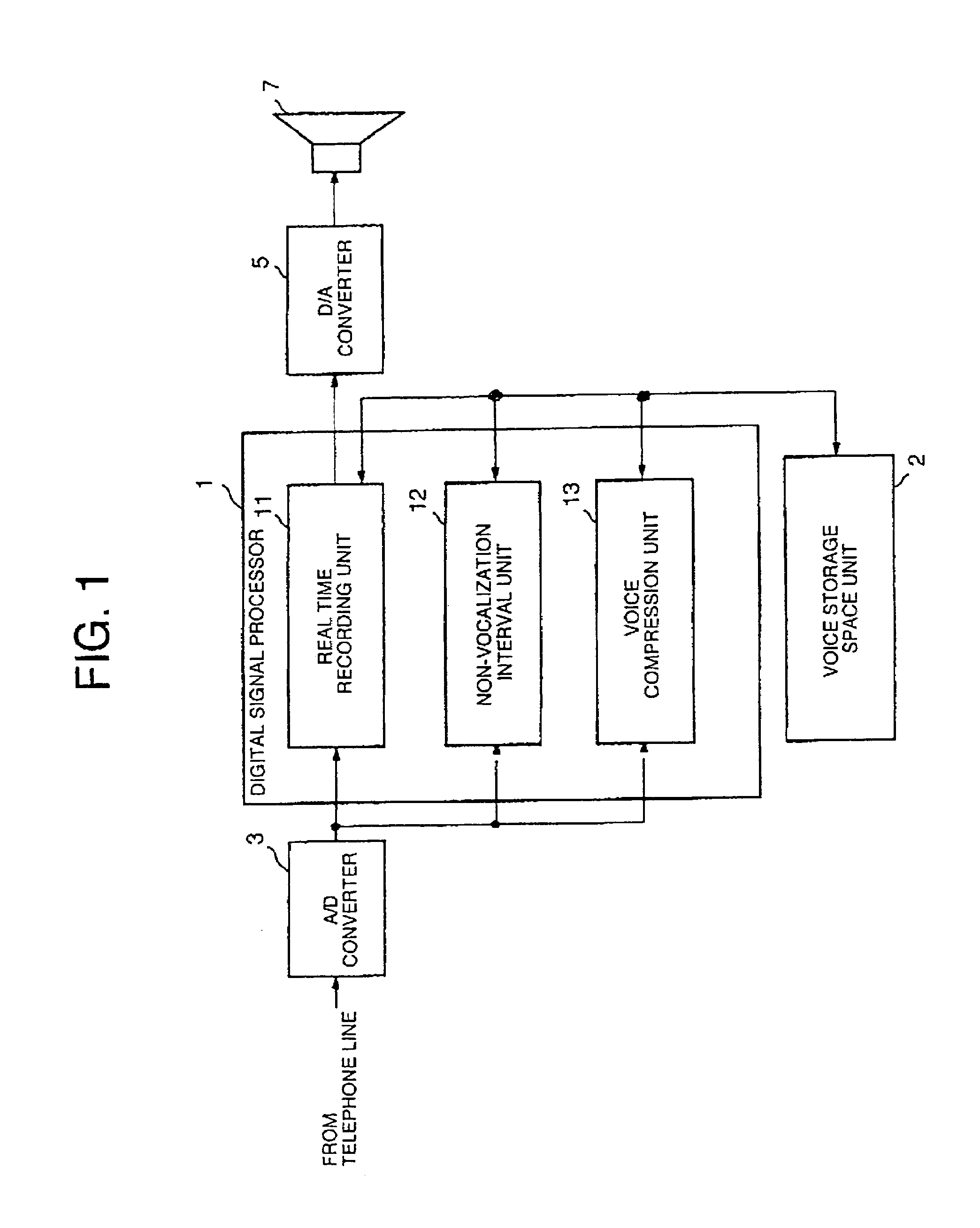
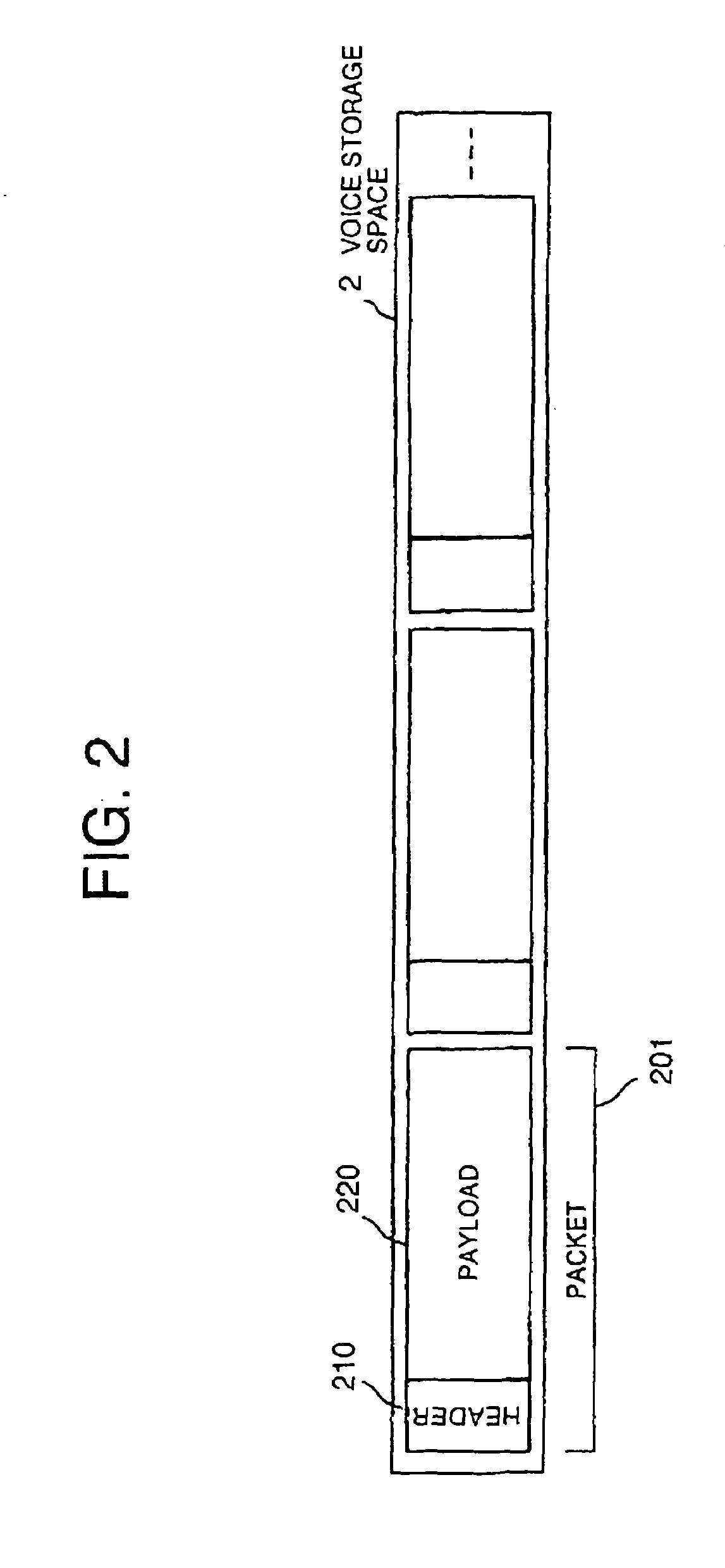
[0023]FIG. 1 illustrates a schematic configuration of a telephone answering device including a digital signal processor 1 and a voice storage space 2. The voice storage space 2 adopts a semiconductor memory conventionally used in recording a coded compressed voice in order to record the codes by the PCM. FIG. 2 illustrates a configuration of the voice storage space 2 inside the semiconductor memory, which is intended to implement the first embodiment. The voice storage space 2 stores plural packets 201. Each packet is configured with a variable length header 210 and a variable length payload 220, and is generated by the digital signal processor 1 or a packet generation means (not illustrated) individually provided thereto.

[0024]A voice is divided into ...

second embodiment

(2) Second Embodiment

[0055]Next, the second embodiment of the voice storage device and the voice coding device according to the invention will now be discussed with reference to the accompanying drawings. The second embodiment is an improvement from the first embodiment in regard to the voice compression block 13, and the voice compression block 13 will mainly be described.

(2-1) Configuration of the Second Embodiment

[0056]FIG. 12 illustrates a voice compression block 13 that implements the second embodiment. A voice decoder 1305 decodes and expands a voice packet that has been coded and compressed. A linear predictive analyzer 1307 analyzes the formant characteristic of a voice. A switch 1306 switches a signal to be supplied to the linear predictive analyzer 1307 in accordance with the contents of the voice packet. An LSP converter 1308 converts the linear predictive parameter (LSC parameter) into the linear spectrum versus parameter (LSP parameter). An LSP quantization table genera...

third embodiment

(3) Third Embodiment

[0065]Next, the third embodiment of the voice storage device and the voice coding device according to the invention will now be discussed with reference to the accompanying drawings. In the third embodiment, the 8 kbps CELP coding and the 4 kbps CELP coding in the first embodiment are configured with a hierarchical coding.

(3-1) Configuration of the Third Embodiment

[0066]FIG. 13 illustrates a configuration of the hierarchical coding that implements the third embodiment. A linear predictive analyzer 1001 and an LSP converter 1002 are equivalent to the linear predictive analyzer 1307 and the LSP converter 1308 which have already been described. An LSP quantizer 1003 quantizes the LSP parameters obtained by the LSP converter 1002. An LSP multi-stage quantizer 1004 quantizes the quantization errors of the LSP quantizer 1003 still more accurately. A pitch analyzer coder 1005 attains pitch components in the linear predictive errors, and configures a pitch synthesizing f...


PUM

PropertyMeasurementUnit
timeaaaaaaaaaa
residual quantityaaaaaaaaaa
voice recording timeaaaaaaaaaa

Abstract

The voice storage device of the invention includes a storage means that stores a voice signal, and a voice compression means that compresses the voice signal requiring a re-coding compression, of the voice signal stored in the storage means, in accordance with a compression degree and a significance of the voice signal. The voice coding device includes: an LSP quantizer that quantizes LSP parameters, an LSP multi-stage quantizer that quantizes quantization error components that the LSP quantizer is impossible to express, a pitch component coder that attains pitch components from linear predictive errors, an excitation source coder in which an excitation source is configured with a multi-stage code book, an essential code output unit that outputs a code essential to decoding from the output of the LSP quantizer, the pitch component coder, and the excitation source coder, and a sound quality improving code output unit that outputs a code to improve a decoded sound quality from the output of the LSP multi-stage quantizer and the excitation source coder.

Description

BACKGROUND OF THE INVENTION[0001]The present invention relates to a voice storage device and a voice coding device suitable for use in a digital coding recording type telephone answering device, or the other digital coding voice recorders.[0002]The telephone answering device has been used to be incorporated into a fixed subscriber telephone terminal or a portable telephone terminal. The telephone answering device is a means to record a voice of a message sender in the built-in recording medium (magnetic tape or semiconductor memory), when the terminal user is unable to respond to the telephone call, also called as the voice mail.[0003]In recent years, since semiconductor LSI circuits have become available which can implement a digital signal processing at a low cost, there has been proposed a telephone answering device using the system that compresses a talker's voice by a high efficiency coding algorithm such as the CELP (code excitation linear predictive coding) and stores the res...

Claims


Application Information

Patent Timeline
Patent Type & Authority Patents(United States)
IPC IPC(8): H04M1/64G10L19/00G10L19/002G10L19/07G10L19/16G10L25/78G11B20/10H04M1/65
CPCG10L19/07H04M1/6505G11B20/10527
Inventor YOKOYAMA, ATSUSHI
Owner OKI ELECTRIC IND CO LTD
Why Eureka
Try Eureka