
Method for determining vehicle velocity

a technology of vectorial vehicle and velocity, which is applied in the direction of process and machine control, instruments, navigation instruments, etc., can solve the problems of shortening the stopping distance, and achieve the effect of improving the vectorial vehicle velocity, shortening the stopping distance, and improving the estima

Inactive Publication Date: 2007-01-16
ROBERT BOSCH GMBH
View PDF16 Cites 3 Cited by
  • Summary
  • Abstract
  • Description
  • Claims
  • Application Information

AI Technical Summary

Benefits of technology

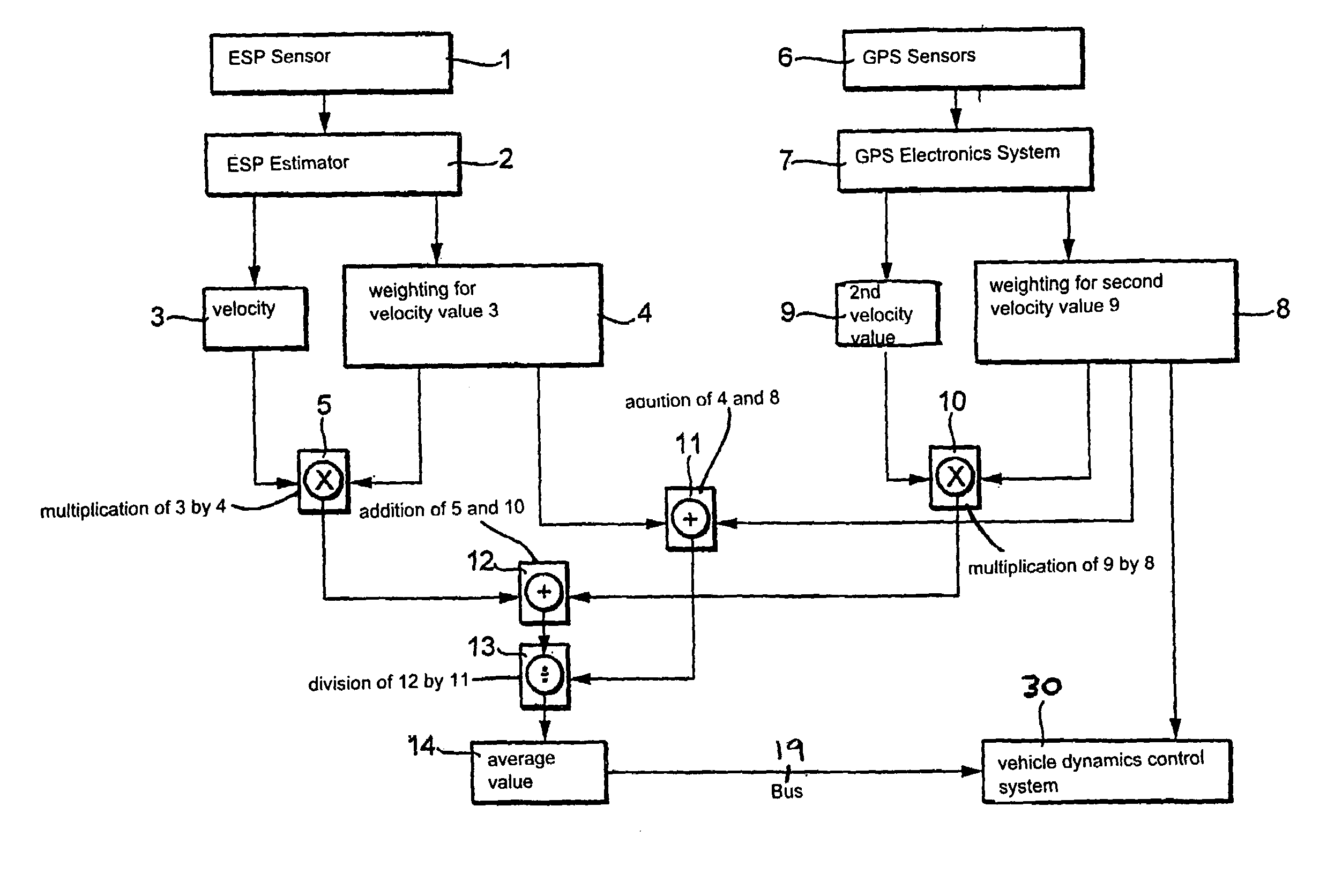
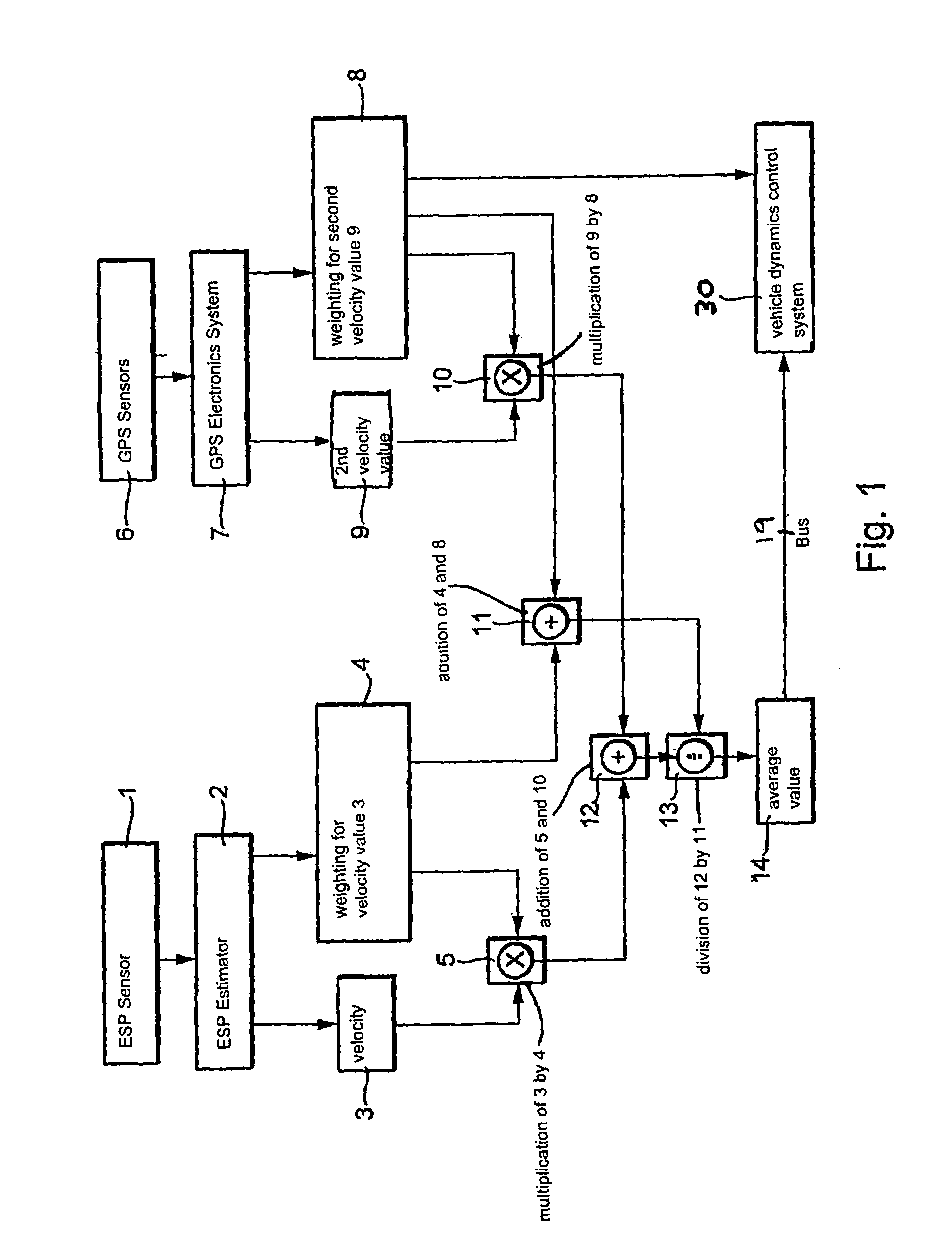
[0003]An exemplary method of the present invention for determining a vectorial vehicle velocity, has the advantage over the related art that the inertial sensors are augmented by the addition of a position-finding device which is used to determine a second value for the vectorial vehicle velocity, in order to produce, by comparing the value that was determined using the inertial sensors and the value that was determined using the position-finding device, an average value that represents a better estimate of the vectorial vehicle velocity. That also makes it possible to dispense with selective under-braking to determine the vehicle velocity, so that such interventions by a regulator are no longer necessary. This results then on the whole in a shortening of the stopping distance. An additional advantage is that the improved vectorial vehicle velocity enables the control of vehicle dynamics by ESP to be improved.
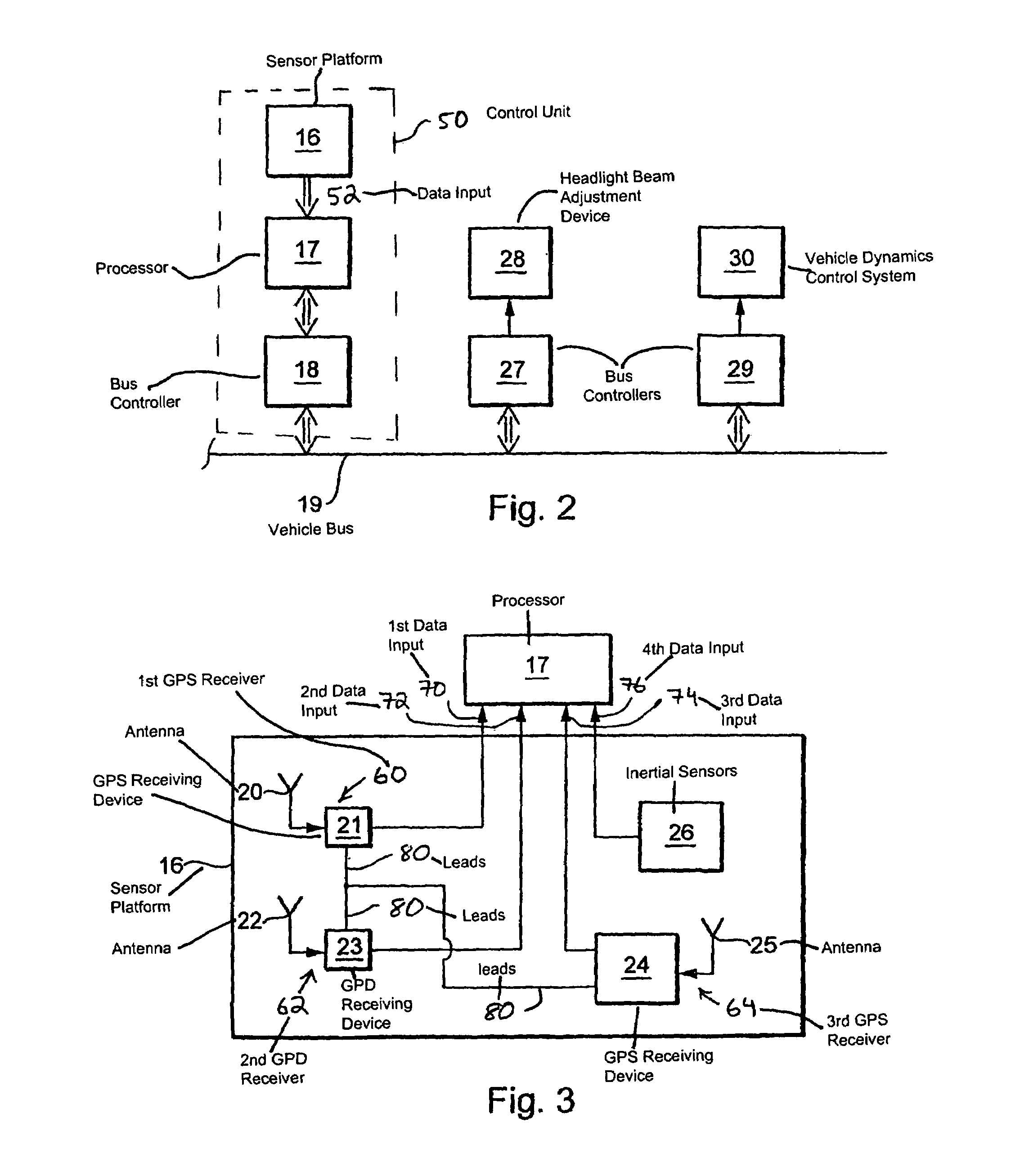
[0004]In an exemplary embodiment the position-finding device is a GPS (global positioning system) which makes possible a very precise determination of position and thus also a very precise determination of velocity. The velocity may be determined from the Doppler effect of the carrier signals or from the carrier phases. A velocity vector is therefore available, because both the magnitude and the direction are thereby determinable as components of the velocity vector. This may be improved by using two or three antennas, so that the orientation is determinable in two dimensions or in three dimensions.
[0005]Furthermore, a vehicle dynamics control system such as ESP is improved thereby, since a maximum number of bits of sensor information are made available to the ESP system. The weighting of the velocity values that have been determined using the position-finding device and the inertial sensors depends on the number of satellites the position-finding device, as a satellite-based system, is able to receive at the time of measurement, the number of antennas used, and in the case of the velocity determined by the inertial sensors, the number of tires that are slipping. Establishing a mean value then makes it possible to estimate the vectorial vehicle velocity as precisely as possible.

Problems solved by technology

This results then on the whole in a shortening of the stopping distance.

Method used


Image

  • Method for determining vehicle velocity
  • Method for determining vehicle velocity
  • Method for determining vehicle velocity

Examples


Embodiment Construction

[0010]For some time the suppliers of vehicle manufacturers have been working intensely on vehicle systems that are intended to stabilize the vehicle states in situations of borderline vehicle dynamics. ABS (anti-lock brake system), TCS (traction control system or ASR (anti-slip regulation)) and ESP are employed. The sensor technology on which such systems rely includes primarily yaw rate sensors, transverse acceleration sensors, and sensors of wheel rotation speed, brake pressure and steering angle. These sensors make it possible to determine the driver's intention in regard to direction and acceleration / braking, and on this basis the motion state of the vehicle is determined. Essential variables for correctly regulating the state of the vehicle are the vehicle velocity, the yaw rate and the float angle of the vehicle.

[0011]Control units are now able to have an intelligent sensor platform, where such a sensor platform represents an integration of inertial sensors, i.e., linear accel...


PUM


Abstract

A method and device for determining a vectorial vehicle velocity by estimating a mean value for the vehicle velocity by using a position-finding device to obtain a first value, and to then compare this first value with a second value estimated using inertial sensors.

Description

FIELD OF THE INVENTION[0001]The present invention is directed to a method and device for determining a vectorial vehicle velocity.BACKGROUND INFORMATION[0002]It is already discussed in the German patent application DE 10049905 (not a prior publication) to employ a kinematic sensor platform in a control unit, where the kinematic sensor platform includes inertial sensors such as acceleration sensors and rotational speed sensors. That makes it possible to determine a value for the vectorial vehicle velocity. This value can be supplied to a vehicle dynamics control system (ESP=electronic stability program), so that an ESP regulates the vehicle dynamics according to the sensor values. This related art therefore leads to the object of improving the determination of the vectorial vehicle velocity.SUMMARY OF THE INVENTION[0003]An exemplary method of the present invention for determining a vectorial vehicle velocity, has the advantage over the related art that the inertial sensors are augmen...

Claims


Application Information

Patent Timeline
IPC IPC(8): B60T8/32G06D7/00B60T8/172G01P7/00G01P13/02
CPCB60T8/172G01P13/02G01P7/00B60T2210/36B60T2250/04
Inventor ARNDT, DIETMARFOERSTNER, DIRKLUTZ, MARKUSAHMED, JASIM
Owner ROBERT BOSCH GMBH
Learn More