Small-scale gas liquefier

a gas liquefier, small-scale technology, applied in the direction of machine operation mode, lighting and heating apparatus, container discharge method, etc., can solve the problems of bringing the cost of the cryogenic system close to that of the home refrigeration system, the new cooler cannot be adapted for these liquefaction purposes, and the implementation of the liquefaction process is not easy

Active Publication Date: 2007-01-23
MMR TECH INC
View PDF10 Cites 36 Cited by
  • Summary
  • Abstract
  • Description
  • Claims
  • Application Information

AI Technical Summary

Benefits of technology

[0004]A dramatic improvement in the efficiency and reliability of a new class of low-cost cryogenic coolers, Kleemenko cycle coolers, opens the possibility that some of the problems discussed above may be overcome. These new coolers, however, can not be adapted for these liquefaction purposes without attending to several issues. For example, when used as liquefiers, these coolers have a number of limitations that demand a different approach for the liquefaction of gases from that of traditional industrial liquefiers. Furthermore, their use in an office environment introduces special safety and handling concerns different from those in an industrial environment. In addition, the small scale of the machine and mode of operation imposes other constraints on the implementation of the liquefaction process. On the other hand, this difference in scale enables the use of novel means for addressing some of the classic problems of the liquefaction of gases such as nitrogen, oxygen, argon and natural gas. The present invention includes the design of a small gas liquefier that takes these various factors in to account and enables the construction of a practical device that meets the needs of the market.
[0005]According to one embodiment, the design and construction of an office, or home scale cryogenic liquefier makes possible the safe, efficient, and convenient liquefaction of nitrogen, oxygen, natural gas, and some other gases. An enabling technology for the development of such a liquefier is the successful implementation of a refrigeration system using a multi-component, mixed refrigerant, single-stream, cascade, throttle-expansion refrigeration cycle, known as the “Kleemenko-cycle” after its originator A. P. Kleemenko, who first described this refrigeration cycle in Proceedings of the Xth International Congress of Refrigeration, Copenhagen 1, 34–39 (1959), Pergamon Press, London. Improving on Kleemenko's ideas, W. A. Little in U.S. Pat. No. 5,617,739 (1997), and W. A. Little and I. Sapozhnikov, in U.S. Pat. No. 5,724,832 (1998), developed self-cleaning techniques that enable these systems to operate continuously for tens of thousands of hours at cryogenic temperatures with no change in performance or need for maintenance, as documented in Little, W. A., Kleemenko Cycle Coolers: Low Cost Refrigeration at Cryogenic Temperatures, Proc. Seventeenth International Cryogenic Engineering Conference, Eds. D. Dew-Hughes, R. G. Scurlock, and J. H. P. Watson, Institute of Physics Publishing, Bristol (1998), 1–9, and in Little, W. A., MMR's Kleemenko Cycle Coolers: Status, Performance, Reliability, and Production. M-CALC IV, Fourth Workshop on Military and Commercial Applications of Low-Cost Cryocoolers, Strategic Analysis, Inc., Nov. 20–21, 2003. The use of common domestic refrigerator components, such as compressors, copper fittings, condensers, and such like, in the fabrication of the coolers have brought the cost of the cryogenic system close to that of home refrigeration systems. In addition, the design of efficient refrigerant mixtures based on ideas of A. P. Kleemenko and implemented using a procedure described by W. A. Little in U.S. Pat. No. 5,644,502 (1997), and similar procedures described by J. Dobak et al. in U.S. Pat. No. 5,787,715 (1998), has dramatically increased the efficiency of these coolers enabling a significant reduction in the size of the device. Accordingly, the above referenced patents are hereby incorporated by reference.

Problems solved by technology

These new coolers, however, can not be adapted for these liquefaction purposes without attending to several issues.
For example, when used as liquefiers, these coolers have a number of limitations that demand a different approach for the liquefaction of gases from that of traditional industrial liquefiers.
In addition, the small scale of the machine and mode of operation imposes other constraints on the implementation of the liquefaction process.
The use of common domestic refrigerator components, such as compressors, copper fittings, condensers, and such like, in the fabrication of the coolers have brought the cost of the cryogenic system close to that of home refrigeration systems.

Method used


Image

  • Small-scale gas liquefier
  • Small-scale gas liquefier
  • Small-scale gas liquefier

Examples


Embodiment Construction

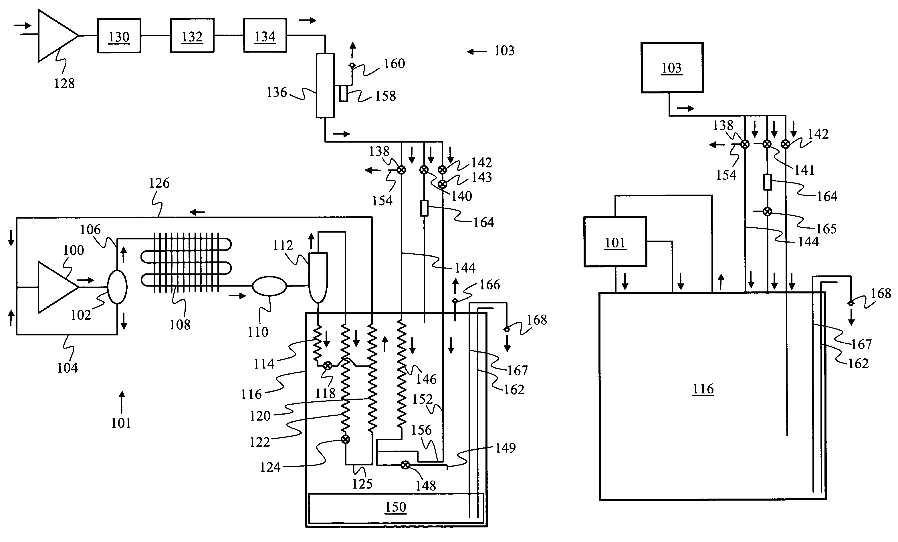
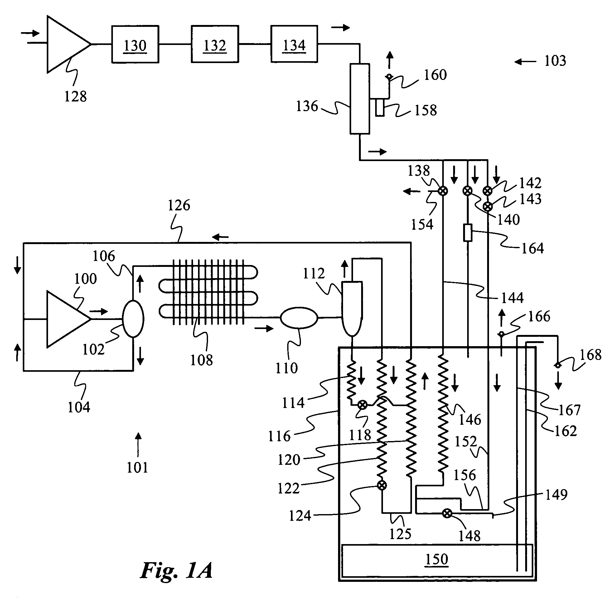
[0012]A schematic of a device for the liquefaction of nitrogen according to a preferred embodiment of the invention is shown in FIG. 1A. Although the following description will focus on a device designed for the liquefaction of nitrogen, a the device may also be used for the liquefaction of oxygen or the other cryogenic gases. In such cases, the operating temperature is suitably adjusted and the refrigerant mixture is optimized to match the liquefaction temperatures of the particular gas to be liquefied.

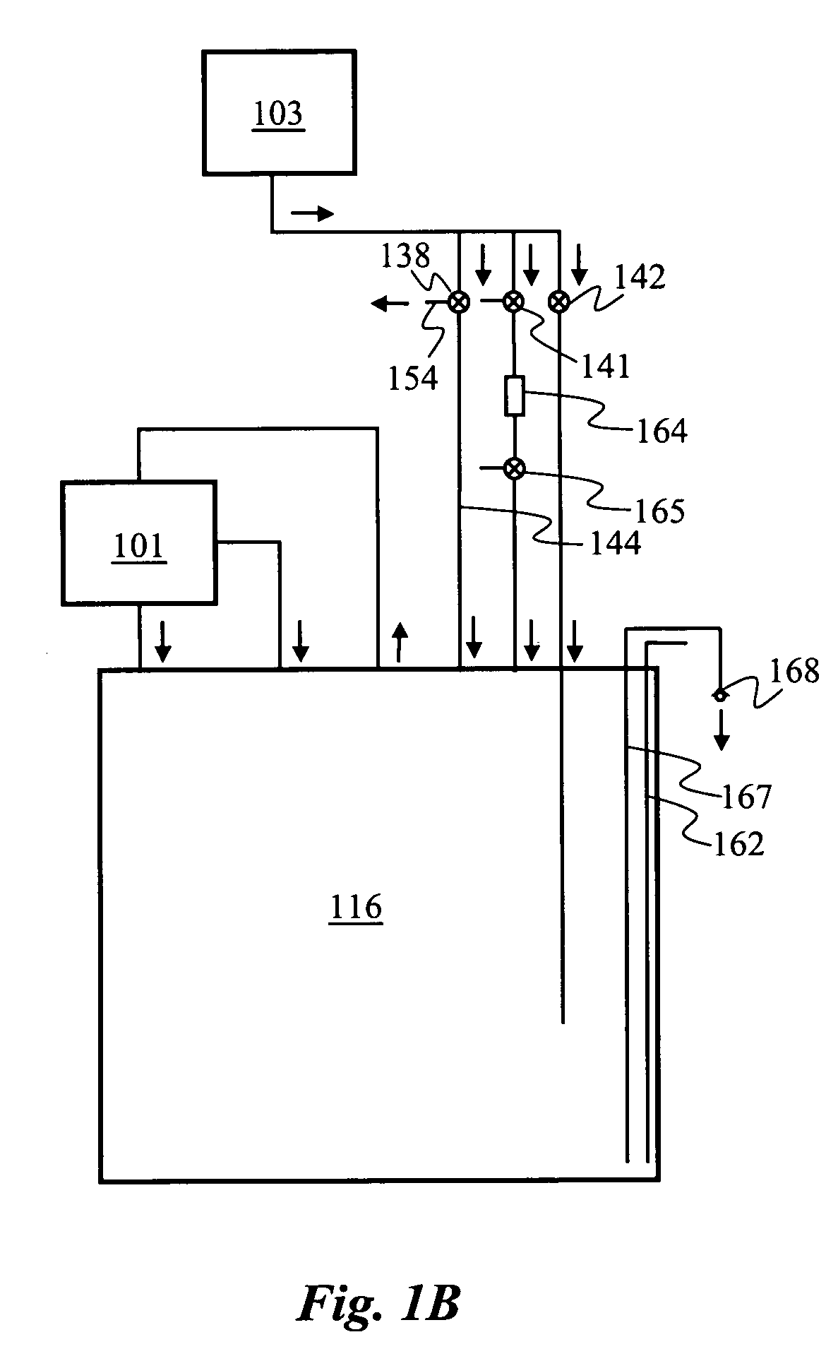
[0013]We consider now the nitrogen liquefier device. The device has a nitrogen gas supply system 103 which has a first section outside dewar 116 where the gas is purified and compressed and a second section inside dewar 116 where the gas is cooled and condensed. Similarly, a cryogenic refrigeration system 101 has a warm section outside dewar 116 where the refrigerant is compressed and a cold section inside dewar 116 where the refrigerant expands and provides cooling. The refrigeratio...


PUM


Abstract

A cryogenic gas is liquefied using a refrigeration system [101] thermally coupled at an evaporator [125] to a cold end of a gas supply system [103] within a dewar [116]. The refrigerator has a minimum temperature at an evaporator [125] above the boiling point of the gas at atmospheric pressure but below the boiling point of the gas at a high pressure. Thus, the gas is compressed [128] to high pressure so it condenses when cooled by the evaporator [125]. As it expands at a flow restrictor [148], a portion evaporates and cools a fraction to the temperature of the boiling point of the gas at atmospheric pressure, producing liquefied gas. Opening a purge valve [142] sends warm gas upward through heat exchange section [146] and out through a three-way valve [138] for defrosting. To reduce clogging, the gas supply valve [138] is controlled by a gas purity sensor [158].

Description

CROSS-REFERENCE TO RELATED APPLICATIONS[0001]This application claims priority from U.S. provisional patent application No. 60 / 626,221 filed 8 Nov. 2004, which is incorporated herein by reference.FIELD OF THE INVENTION[0002]The present invention relates generally to techniques for the liquefaction of cryogenic gasses such as nitrogen, oxygen, argon, methane, and other similar low-boiling-point substances. More specifically, it relates to small-scale cryogenic gas liquefiers that are inexpensive and simple to operate.BACKGROUND OF THE INVENTION[0003]Shortly after nitrogen and oxygen were first liquefied in the last 1800's, industrial production of liquid nitrogen and liquid oxygen was accomplished and they rapidly became important commodities for the steel and fertilizer industries. Economies of scale reduced the cost of liquid nitrogen and liquid oxygen to a few cents per liter. Thousands of tons of each are now produced per day for industrial purposes and are transported over large ...

Claims


Application Information

Patent Timeline
Patent Type & Authority Patents(United States)
IPC IPC(8): F25J1/00A61M11/00F25B19/00
CPCF17C7/02F25J1/0015F25J1/0017F25J1/0055F25J1/0097F25J1/0212F25J1/0225F25J1/0248F25J1/0251F25J1/0276F25B9/14F25J2210/40F25J2205/24F25J2220/44F25J2270/908F25J2270/91F25J2205/40F25J2205/80F25J1/00
Inventor LITTLE, WILLIAM A.
Owner MMR TECH INC
Why Eureka
Try Eureka